Chapter Three: after the War, before Washington
By the end of the Great War and with the defeat of Germany suddenly there was a huge shift in the balance of naval forces of the World. The former enemy, the German Kaiserliche Marine’s ‘Hochseeflotte’ was interned and was rusting away in Scapa Flow (until it sank itself in June 1919). In Europe this meant that the RN was the undisputed ruler of the seas. This was a false image however. At least a third of it’s core naval force, battleships and battlecruisers sported 12″ guns only which were a magnitude weaker in every aspect compared to the 13.5″ and 15″ guns of the ships commissioned right before and during the war. These old, first generation dreadnoughts could not be counted on for long, especially that these units had the most mileage on them – no wonder that all decommissioned not much after the conflict’s end. Unfortunately for the RN even her more modern super-dreadnoughts were getting obsolete as well due to the increased firing ranges combined with much better fire-controls – but especially the newer underwater weapons endangered them.
The DNC realized this threat relatively early on so at least the then building HOOD could be equipped with the most modern torpedo defense system and the R class battleships were retrofitted with a somewhat less refined type. HOOD represented the highest level of the incremental armor protection school meaning that it had the best multi layer, multi thickness armor in the navy. As such she was the most powerful warship in existence and the future pride of the RN – but she was still building and alone.
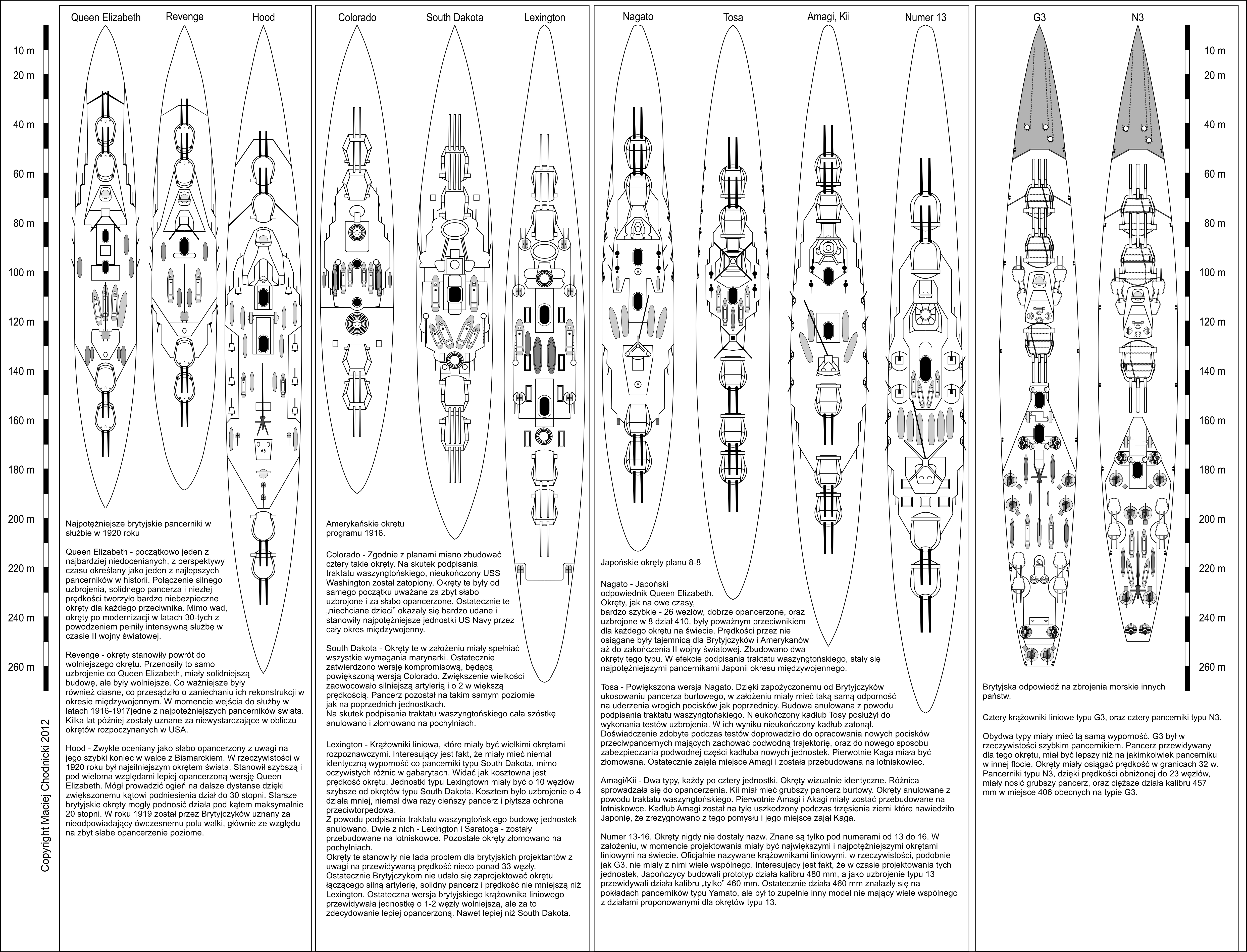
By 1919 two new naval challengers emerged on the horizon: the Nihon Kaigun (Imperial Japanese Navy) and the United States Navy. In an ugly twist of fate both organizations were largely trained up and helped by the Royal Navy itself. They mentored the Japanese for decades, supplied them with parts and even complete warships. Uncle Sam got all their war experience and even the complete plans for HMS HOOD on silver plate: chief constructor Sir Stanley Goodall temporarily worked with the US Navy’s Preliminary Design branch in the later part of the war. In return at least the British had a fairly good idea about the latest and greatest American units. Thanks to this they could plan what the near future of naval warfare might bring and what their likely opponents can bring to battle. The six LEXINGTON class battlecruisers (CC 1-6) then building in the States had a planned top speed of 33,5 knots, clearly outclassing HOOD’s 31,5 knots, what’s more their main armament of eight 16″/50 Mark 2 guns potential firepower placed these ships in a class of their own. The concurrently building SOUTH DAKOTA class battleships (BB-49-54, six units again) were armed with twelve such weapons, per hull. The SoDak’s speed was 23,5 knots meaning that only the QUEEN ELIZABETH class ships and HOOD had the capability to match them in speed and protection. If this all would not have been enough the US ships then in service or finishing construction (especially the TENNESSEE and COLORADO class units) were worthy opponents as well, they were equal in protection and firepower and had better torpedo defense systems compared to Royal Navy super-dreadnoughts (again HOOD was the sole exception).
Japan, although wielding less industrial and military muscle, was a more likely opponent (so the British thought) as they have copied everything from the RN and there was no doubt that they will try to outsmart their masters sooner or later, at least in the Far East and the Pacific. Probably the Royal Navy did not posses as detailed information about the future Japanese ships as the US ones but thanks to years of cooperation with Admiral Hiraga and other Japanese naval architects they knew that by now the Nihon Kaigun had the know-how to design and construct first rate ships. In 1919 the cutting edge Japanese unit was battleship NAGATO (not completed yet) which was essentially an enlarged QUEEN ELIZABETH with 16.1″ guns and even higher speed (26 knots), pretty similar actually to what the British constructors had in mind during the preliminary phase of the HOOD design process (see Part 1). The Japanese realized the tactical advantage offered by high top speed so they planned all their future units accordingly. Furthermore the Nihon Kaigun, thanks to it’s relatively young status as a tier 1 navy, had no old ships draining away money and effort so even with their more limited resources they could focus on building more powerful new ships. The TOSA class battleships (2 units) and AMAGI class battlecruisers (4 units) under construction sported ten of the deadly 16.1″ guns per hull, leaving no doubt about the future power of these ships among those few who knew this detail. All these warships were capable of at least 27 knots top speed, again meaning that HOOD was the sole counterbalance in the Royal Navy.
In early 1919 it was in this international naval climate that a committee chaired on the future of the Royal Navy and investigated what steps should be taken to counter the new challengers.
Before we proceed with the exact answer we have to take a look at the changes and progress impacting naval guns and armor in this period.
Editor’s note: below I have used the metric format of all values except for gun names where I refer to them with the original, official format
Superheavy guns, extra size torpedoes and ultra thick armor
During the design of a gunship the first and foremost factor is the selection of armament, thanks to battleships being weight critical – that is based on the equilibrium between the heavy weights installed in and on the hull. The caliber of the main armament pretty much defines all other factors, like the armor thickness needed for protection, how much weight is left for machinery, what barbette diameters are required which in turn defines the minimum beam and a host of other, interrelated factors.
For the future battleships the British wanted 18 inch/457mm guns mainly in order to surpass the foreign ships then under construction. However in 1919-20 only the Elswick armament company had tools and machines big enough to take on such a gun project whereas 16 inch weapons could be sourced from multiple vendors.
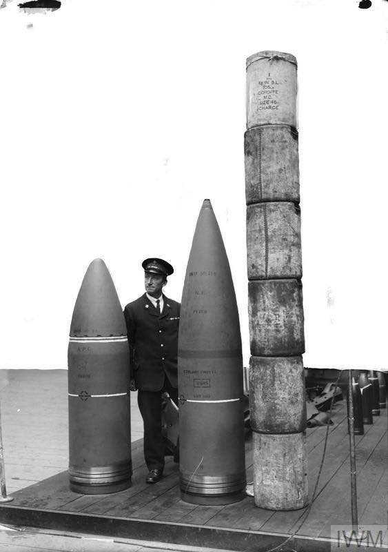
The good old, venerable 381mm, 100 ton Mark I 15″/42 gave the better part of the firepower of the British battlefleet.[1]This otherwise exceptionally good weapon could fire an 870kg AP shell with a muzzle velocity of 753m/s towards a target. In contrast the American Mark 2 16″/50 with it’s 137t own weight could hurl a 952kg shell at 838 m/s which clearly outlcassed the British gun. What was more alarming is that even the older, shorter Mark 1 16″/45 could do 792m/s with the same ammo!
Fortunately the British had an experimental 457mm weapon, manufactured by Elswick around the end of the war. This gun was essentially a scaled up version of the 15″/42 Mark I with a simple proportional expansion of physical dimensions and this yielded the Mark I 18″/40 (cover name 15inch B – see Part 1). Only 3 examples of this mindblowingly powerful weapon were completed which could fire a 1505kg AP shell, though the muzzle speed was a measly 693m/s. This was due to the short caliber length and low quality MD45 named cordite. In reality only HMS FURIOUS and two monitors [2] equipped the completed examples although several preliminary plans mentioned this gun as a primary armament (see Part 1 again).
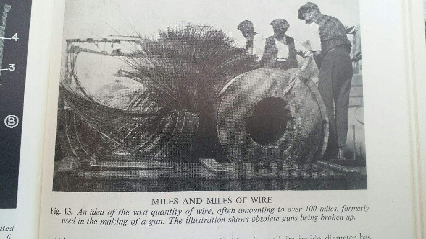
In November 1919 the request for proposals went out to design and build a 457mm/45 naval rifle. 3 prototypes were requested with 3 different manufacturing processes: the first with the traditional British wire-wound construction, the second with an all steel construction and the third, with a middle ground solution where the wiring was done up to the middle of the barrel only. The wire-wound process was introduced by the British to increase cross sectional structural strength so in essence the barrel could take higher gas pressures (and higher muzzle velocity in turn) without expansion. The method involved the wrapping (wounding) of an extremely long wire around the inner structural or A-tube of the gun which was then covered by an outer layer (jacket). The drawback of this method however was that longitudinally the barrel was more prone to drooping or to any other deformation. Basically that is why most of the British major caliber guns of the period had a maximum caliber length of 45 or even 42 only. Anything longer than this and drooping became an issue (see the Mark XI 12″/50). In contrast the more ordinary all-steel construction required thicker walls for the barrel and meant a comparatively heavier gun for it’s caliber which in turn meant other problems during manufacturing in case of extra big calibers (like in our case). After all a fourth type was planned which would have used the Krupp patented built-up method where the parts of the barrel were machined separately and were assembled together with a precision method.
They counted with the serial production guns being all wire-wound since the the other two types would not have been ready in time and finally the Woolwich designed contender had a relative low weight of 134.5 tons, so this gun could have fired the 1505kg AP shell at 762 m/s. Later after some firing trials the navy decided to adopt lighter shells to attain higher mv.-es with all guns, so a 1322kg AP shell was introduced that had a theoretical mv. of 807 m/s with said gun. There appeared to be a solution for the MD45 cordite issues as well so good progress was made overall but in January 1922 the Washington Treaty ordered all construction work to stop on these weapons.
It is worthy to note that even in 1920 murmur was going on about possible 508mm or even 533mm (20″ or 21″) shell manufacturing but the Admiralty soon put an end to this in order not to further escalate the caliber race with the US. Actually the Elswick company had the means to construct such a weapon, a 508mm/42 cal length weapon being the maximum their shops could have handled at the time. The British quite probably knew (from Goodall) that the US Navy had at least one prototype 457mm gun[3] (18”/48 Mark 1, 1315 kg shell, 823 m/s mv, 178 ton weight!) and that they had initial plans for a 508mm one. What’s more there was some trickling info from Japan as ell that they have test fired a 480mm (approx. 19″) gun, though it split in two pieces during the process. Other than this the only known super gun project was the French Mk 1920A 450mm/45 (17.7″) developed by the Schneider company. This was quite probably unknown to the Admiralty as details were unearthed just recently. This gun was supposed to be capable of 875 m/s with a 1350-1400 kg AP shell, all this on 128 tons.
Despite the massive caliber race the British designers soon realized that such guns would be overkill for their future battlecruisers (as we will see shortly) so alternatively they looked at using theoretical 381mm/50, 419mm/45 and 419mm/50 (16.5″) guns as well. These stood in line with the 1.5″ caliber steps they used (12″-13.5″-15″-16.5″-18″). In the end they still decided for a 406mm (16″) weapon which was again manufactured by Elswick based on Woolwich plans and it ended up as the main armament for battleships NELSON and RODNEY as the British Mark I 16″/45. It could do 823 m/s with a 928 kg shell while coming in at only 108 tons, thanks to the wire-wound construction method (by the way this was the last such British gun). The first tests were not too promising with the test gun doing only 813 m/s muzzle speeds on average and showed excessive barrel wear which lead to decreased accuracy in addition. This turned out to be due to the short body-long head shell which tended to wobble or hammer the barrel. The solution was simply to lower muzzle velocity to 815 m/s and to apply a new grooving pattern to the barrel which actually gave back 7,5 m/s.
The classic WW I issues were ironed out by 1920 (like the inferior quality AP shells and unstable cordite) but a major question still remained: is the heavy shell-low muzzle velocity or the light shell-high velocity combination the better solution? Tests done right after the war and experience learned from the Germans showed that the latter is better, even though the lighter shell lost more of it’s inertia on longer ranges and it did not gain back as much speed on the downward part of it’s ballistic trajectory either. The heavier shells tended to brake or ricochet on more oblique impacts due to their usually longer bodies. Therefore the former, heavy or normal 18″/457mm shell was redesigned from 1505kg to a meager 1322kg while the 16″/406mm thinned to 928kg from 1056kg. Later tests in 1922-23 showed that with redesigned AP and ballistic caps the heavier shells could handle higher oblique impact angles (25-30°) just as well with all other advantages remaining – still the RN stayed with the lighter shells.
| Navy, Gun
(actual caliber) |
AP shell weight (kg) | Muzzle velocity (m/s) | Muzzle energy (MJ) |
| USN 16”/45 Mark 1 (406mm) | 952 | 792 | 299 |
| USN 16”/50 Mark 2 (406mm) | 952 | 838 | 334 |
| USN 18”/48 Mark 1 (457mm) | 1315 | 823 | 445 |
| USN 20”/45 Mark 1 * (508mm) | 1860 | 792 | 583 |
| RN 15”/42 Mark I (381mm) | 870 | 753 | 247 |
| RN 16”/45 Mark I (406mm) | 928 | 823 | 314 |
| RN 16.5”/45 Mark I *(419mm) | 1158 | 727 | 306 |
| RN 18”/40 Mark I (457mm) | 1506 | 683 | 351 |
| RN 18”/45 Mark II (457mm) | 1323 | 808 | 432 |
| MN 450mm/45 Mk 1920A (450mm) | 1366 | 875 | 523 |
| KM 420mm/45 SK L/45* (420mm) | 1030 | 800 | 330 |
| NK 41cm/45 Type 40 (410mm) | 1020 | 790 | 318 |
| NK 48cm/45 Type 36 (480mm) | 1770 | – | – |
| NK 46cm/50 Type 46 (460mm) | 1550 | 800 | 496 |
| Vickers 16”/45 exp. (406mm) | 1116 | 757 | 320 |
Naval guns of the World in existence or planned in 1920 that had a caliber of at least 400mm or greater. The items marked with a * existed on drawing boards only, their shell weight and muzzle velocity is an estimate. All the rest of the guns in the table had at least one example’s construction started. The British ’15″/42 Mark I’ and the ‘Vickers 16″/45 export’ weapons got included as a reference: the former made up the main armament of the RN’s battleships and HMS HOOD while the latter was the biggest gun the British gun manufacturers have produced and was not commissioned by the RN. Muzzle energy is not an exclusive performance indicator but shows the relative power of these weapons very nicely.
USN – United States Navy (blue); RN- Royal Navy (light blue); MN – Marine Nationale (pink); KM – Kaiserliche Marine (grey); NK – Nihon Kaigun (red)
The other important question beyond the caliber of the main battery was the number of guns and their turrets. The units built before and during the Great War had exclusively two barrels mounted per turret which allowed for simpler, lighter mountings and smaller barbette diameters. An other advantage was that in case of a hit on a turret only a lesser percentage of the battery fell out, provided the turrets had ample spacing. Actually during the BELLEROPHON class’ design process the idea of the triple turret came up (see Part 1. for the ‘X4 Fusion’ design) and later it re-surfaced during the HOOD’s long gestation period. Other navies used triple turrets for quite some time (USN, A-H’s KuK Kriegsmarine, Regia Marina) and the French even designed a quad turret, though in reality that was a double twin. In the above mentioned design scenarios the idea was discounted however due to lack of time and experience. Despite it’s drawbacks (heavier rotating weight, larger deck cutouts due to bigger barbettes) the triple or 3-gun turret had one critical advantage: the same number of barrels could be housed in a smaller space and that in turn allowed for a shorter hull and citadel and less armor weight to cover the vitals. In practice it meant that in case of a 50.000 ton battleship the 3 by 3 arrangement allowed for one extra gun shipped over classic 4 by 2 layout and still saved a good 1000 tons that could be spent on extra armor.
Finally the mounting designed by Elswick again won over the competing Vickers one, both for the 406mm and 457mm turrets (other sources mention Armstrong as the winner for the 406mm turrets). The latter, bigger turrets’ drawings did not survive but it is assumed that generally it followed the design of the 406mm one with a rotating weight of 1700-1730 tons and a roller path diameter of 11.4m (12.2m barbette dia.). The little brother weighed in at 1560 tons on a 10 m roller path in a 11.7m barbette. (When later fitted to NELSON class battleships the weight had to be reduced further to 1464 tons.) The main difference between the two turrets was that the 457mm one’s ammo handling was fully mechanized. In both cases maximum elevation was set at 40° and loading elevation at 3°.
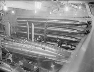
Next to gun development some serious work went into the other major weapon system of capital ships (as it was though at that time) the heavy anti-ship torpedo. Finished only by 1924 the Mark I 24.5″ (62cm) oxigen driven super-torpedo could deliver a 340 or even a 445 kg charge to 13.7 km with a speed of 35 knots, unheard-of performance in those days. If speed was reduced they could go out to a sensational 18.2km, easily into gunnery range territory experienced during the war. The smaller, 21″ (53cm) variant developed for cruisers and destroyers got cancelled as the pure oxygen fueled drive system posed some extreme dangers to the carrier vehicle as well. So it remained for the Japanese 20 years later to demonstrate the power and dangers related to these weapons, although the RODNEY fired her torpedoes in real action against BISMARCK though no sources credit her with a confirmed hit.
Finally we arrived to the other major, vital component of capital ships: the armor. Former fleet units of the Royal Navy did not represent the cutting edge in protection (especially compared to German ships) though the more modern units were certainly up to anyone’s standards of the day. The major shortcoming (not unique to British ships) appeared to be the insufficient turret top and armor deck thicknesses. Also earlier ships were lacking in the torpedo defense department as well as pump capacity.
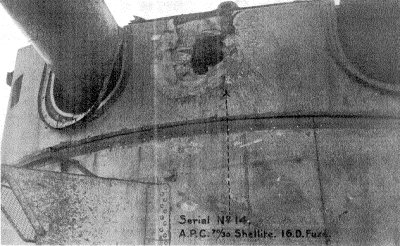
In 1921 the navy conducted a fairly thorough and controlled test shooting against the ex-German battleship BADEN which sunk herself in Scapa Flow but later got raised. This ship represented the latest and greatest that the Imperial German Navy had during the Great War, it’s protection was certainly among the best world wide. The armor steel quality was fairly similar to British standards and the vertical armor was both thicker and covered larger areas compared to Royal Navy ships, though the decks were relatively thin as well. After all it massively followed the incremental armor layout scheme that the German Navy so much preferred – they believed in short range engagements and also expected smaller caliber HE shells as a threat to their BBs. The incremental scheme had both very thick, medium and light armors mixed depending on what importance the protected part had. It offered better protection vs HE shells and covered larger areas but usually it meant that a given hull size/weight could carry less armament or machinery to compensate for the heavier total armor weight. At Jütland German ships with very similar armor layouts and thicknesses proved to be very hard nuts to crack and some of them survived tremendous amounts of hits – though as we know now many of these shells detonated on impact or very shortly thereafter, largely negating the destructive effect. Also the damage sustained sent these ships to the yards for month as many of their armor plates had to be re-manufactured and replaced. Especially the 381mm shells were very damaging as their sheer kinetic energy proved to be devastating enough. Due to their overall poor performance though the British started to redesign their shells and came up with the 4crh long “Greenboy” family of shells, that were heavier, more stable and had a new fuse design. This 1921 test was conducted exactly with these new shells.
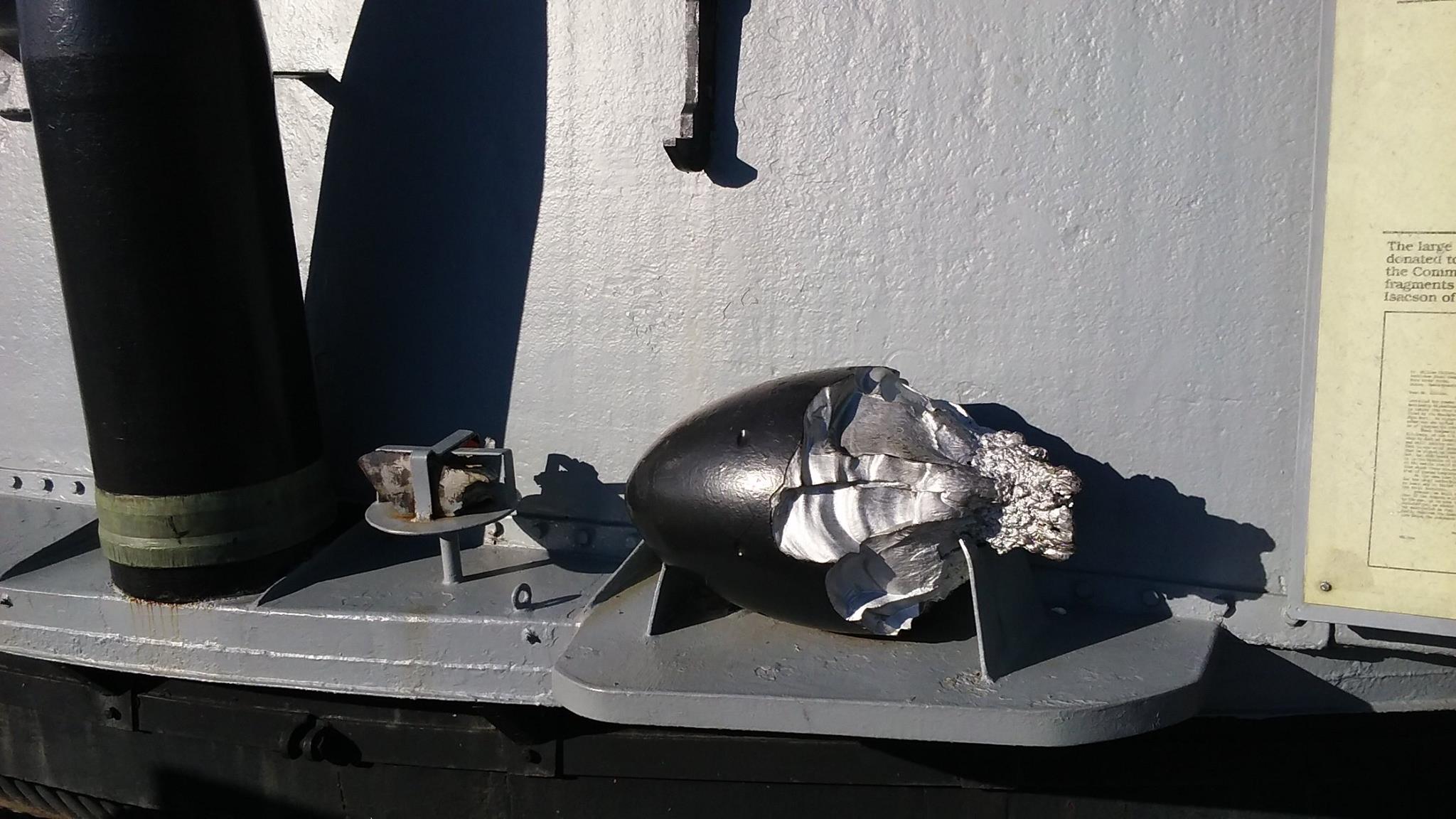
The results clearly indicated the superiority of the new shells and pointed out the need for the “all or nothing” armor scheme that was already used by the USN since the NEVADA class of 1916. The 381mm Greenboys penetrated 250mm of vertical face hardened armor with ease, even from distances as great as 20kms. Actually even BADEN’s 350mm turret face plate was penetrated from a simulated distance of 15kms and at an angle of 18°. A similar shell from an angle of 30° was unable to penetrate the similarly 350mm thick conning tower though, so this was about the upper limit (350mm, <20°obliquity at 15km) for these shells which is pretty good for the day. On the other hand several thinner plates with the same total thickness proved to be much less effective: an other 381mm shell penetrated at a distance of 15km one 250mm upper armor belt plate at 14°obliquity then went through the 30mm splinter bulkhead (armored) and the 13mm upperd deck armor and detonated 12m behind this on the starboard funnel uptake. The armor flakes created by the shock/spalling effect and the remnants of the shell damaged two boilers. Finally a SAPC shell penned the upper 180mm battery or casemate armor then went through the 180mm lower part of Bruno turret’s barbette all this at an impact angle of 42°- quite impressive! A 1,5 by 1m piece of armor was punched out of the barbette which jammed the turret in train and would have rendered it out of action in a real situation. With reference to the hit on the conning tower it is safe to say that had the barbette been a single 360mm plate instead of two times 180mm it would not have been penetrated at this impact angle.

The takeaway message of the test was still that the turret roof plates and their supporting structures have to be beefed up a lot.
After the shelling some bomb trials came and unlike Billy Mitchell’s stunt show these tests were carefully looked at after each hit. The BADEN fared surprisingly well. The 816, 250 and 235kg bombs detonated directly on the armored decks did negligible damage, only one of the 235kg bombs managed to hole the unarmored deck which it was suspended from.
In the USA around the same time the above mentioned gentleman’s flyboys subjected the battleship OSTFRIESLAND to similar bombing trials. That ship was two generations older and had somewhat lesser protection but even so she showed similar results, only the hammering effect of the biggest, 907kg bombs exploding right next to the hull had enough energy to open it up significantly. The smaller bombs independent of their hit locations were unable to damage the stationary hulk enough to make it sink.
The RN concluded that bombs and their current dropping method (ie. level bombing) did not mean a significant threat to armored capital ships. Not so with torpedoes! A lot of attention was paid to underwater protection against torpedo and mine warheads as in retrospect these proved to be the most dangerous weapons against such big ships during the Great War.
The British solution early on was the use of bulges that were essentially huge double hulls applied onto the existing outer shells of the ship. It was literally formed like a longitudinal bulge to make it hydrodynamically efficient and it usually covered approx. 2/3 of the ship’s total length. The ‘R’ class ships got this first in retrofits and later ships like HOOD had this feature integrated into the original hull right from the design phase. The early versions of the bulge were subdivided longitudinally into parts and fitted with so called crushing tubes that were made out of metal and varied in diameter. These were intended to absorb the shock effect of an underwater explosion. The HOOD’s second generation system had a 38mm main torpedo bulkhead and outboard of this were the crushing tubes then void spaces between these and the outer shell of the bulge. Where space permitted they installed a second, inboard torpedo bulkhead as well (20mm) and fuel tanks inbetween. In it’s deepest parts the HOOD system had a depth of 4m and the whole was considered proof against a 227kg torpedo warhead. Further testing revealed that if the crushing tubes got replaced by water the same effectiveness remained and some weight and in case of damage extra reserve buoyancy gained back. In a further developed version this system constituted the underwater protection of the below detailed ships – in it’s final form it got a proof rating against a 340 kg TNT charge.
Finally a small scale test object representing the design’s cross section with the magazines below the shell rooms -reversing the order compared to earlier ships (except HOOD’s sisters) – was subjected to mine explosion tests. The logic behind the reversion was that the inrush of water would prevent any sort of fire or secondary explosion. In the end a 2,3m deep double bottom was tested against a 158kg mine with the expected results: no fire among the cordite charges.
The new generation
The committee of 1919 reported in March 1920 that despite the new air and sub-surface threats the capital ship is still king of the seas: in other words the big gun – armored warship is still the undisputed cornerstone of any modern fleet intended for open ocean naval warfare. It also meant that the dominant navy needed the best and probably the biggest such ships in it’s inventory that also complied with the latest requirements like overwhelming firepower, outstanding armor and torpedo protection and high speed. In order to attain this latter quality they were willing to give up some of the former two.
Due to this report and the external political situation detailed in the introduction part made it crystal clear to the RN and it’s leaders that they needed new fleet units and they needed them now unless they wanted to risk becoming a 2nd rate naval power behind the USN and the IJN! Therefore 3 battleships and 1 battlecruiser were ratified for the 1920/21 fiscal year which was soon changed to 4 battlecruisers in light of the existing fleet’s obsolescence. Politically this meant the beginning of what we know today as the G3 class battlecruisers and which saw the light of day in the form of the NELSON class battleships after much political influence.
Actually in the background a lot of political fuss was going on within the Navy itself. In the crosshair stood Sir Eustace Tennyson-d’Eyncourt (DNC) and his masterpiece, HMS HOOD and the incremental armor scheme. The opposition’s main spokesperson was the famous Captain Frederick Dreyer who earned his undeniable reputation as the father of centralized fire control that allowed for long range gunnery besides being Admiral Jellicoe’s Fleet Gunnery Officer during the Battle of Jütland.
In his expert opinion the incremental scheme got outdated in light of the increased battle ranges experienced during the war, which were often as great as 18km. Furthermore the majority of the hits would be on the decks in any more distant future battle and the light (<100mm) and medium (100-250mm) armors that made up the majority of HOOD’s vertical protection would be penetrated at any distance, offering no protection against major caliber guns (406mm<). Dreyer suggested the return to the “all or nothing” armor layout of the late 19th century in order to gain weight to strengthen armored decks and turret tops and to use only the thickest plates for vertical protection (albeit on much smaller surfaces, so with less protected volume). Of course the price for this was a massive step backwards in the protection against high explosive and small caliber AP shells – but WWI and recent testing experience showed that the highest caliber APC shells were the most dangerous in terms of damage inflicted. The former view on capital ship protection emphasized the use of the most possible layers of armor in order to localize the damage as much as possible even if the shell penetrated the outer layer(s) as they could hope the fuse would be broken by the time the shell reached the innards of the ship.
Without picking sides it is worthy to point out two important things along the logic of Dreyer’s approach and in my opinion these were largely the points why the Admirals Staff decided for the all or nothing armor.
First if we accept that effective gunnery ranges increased to 15km or more than this factor alone reduces the vulnerability from HE shells – which are usually considered as the Achilles-heel of the all or nothing idea. Due to the increased distances it could be taken almost for granted that hit percentages (already as low as 3-4%) will plummet even further (into the 1% range). At Tsushima the short battle ranges (2-4km) assured that even the smaller quick firing guns can take part in the engagement sending an avalanche of HE shells toward the Russian ships, tearing up and burning their superstructures and unarmored parts with devastating effect to men and moral. Even so only 11 years later at Jütland there was no sign of such hail of small caliber fire between the opposing capital ships: the Germans did not use HE shells for their main guns and their 150mm secondary gun batteries were literally at the very edge of their effective ranges during most part of the daytime battle. The number of hits scored by the Germans was fairly low compared to Tsushima (despite having more ships) and even so 3 British capital ships suffered a devastating end. On the other hand the Brits also suspected that they inflicted massive damage on the other side, despite their even lower overall hit rates. So it seemed fairly logical that in the future the number of major caliber hits will decrease in reverse proportion to the increase in gunnery ranges which pointed immediately to the biggest threat under those circumstances: the large caliber AP shells. It was only logical to make the armor protection viable against this greatest of all threats, even if it meant a considerable reduction of protection vs. HE and smaller caliber AP shells. In other words future battles will be decided by very few but very large caliber shell hits.
On top of this one can not ignore the rapid evolution of naval guns (the very essence of a battleship): while in 1905 major caliber meant 305mm by 1916 this was defined as 381mm and a few years after the war, in 1920 designers could very well expect 457mm or even 508mm guns to enter service during the life cycles of the then to be designed battleships. Such weapons were several times more lethal even with a single hit compared to their predecessors. It just made sense to not only limit or localize damage but to entirely keep out any such projectile so as to avoid a catastrophic result.
This explains the extremely thick armor used on designs detailed below – what’s more the vertical plates were slanted for even greater effect.
Our good, old DNC took these comments as a personal attack and for a reason – he wrote to Dreyer in their correspondence that the performance of the Greenboy shell is a bit overblown and he reasoned that it is very rare for a shell to have to go through only a single plate so that ship protection should be looked at in more complexity (ie. in a system approach where several plates are interacting). Furthermore he argued that impact angles are usually between 20-30° instead of the advertised 0-10° range (close to perpendicular) and this automatically meant a much lower penetration ability.
Despite all this DNC on his very own initiative entertained chief constructor Attwood from May 1918 with working out new ideas, approaches for future capital ship construction.
As we have seen many times so far the first step was based on the hull of HOOD with four variants in one go: in the first two the twin 381mm turrets were changed to triples. With three triples displacement went up to 44.000 tons while speed decreased only marginally; with four triples and keeping the updated HOOD machinery (150k SHP) the proposal grew to 273m waterline length and 50.000 tons. In the next phase three triple 457mm/40 turrets were tried, two forward and one aft. For much of their surprise even this armament fit without any major weight increase if they were willing to give up 4 knots of speed due to the compressed machinery spaces that this arrangement required. With four such turrets length was up again at 273m at 50.000 tons with the same 4 knots slower speed. The HOOD hull shape was by far not the ideal at that point and they tried to fine tune it with things like a transom stern.[4]
All in all it was getting all too clear that the HOOD design is outdated as hell and something new has to be tried, which Attwood played with. Since in the past the length of the most heavily armored middle part, the citadel (which was covered by the main belt and deck armor) was defined by the buoyancy levels needed to keep the hull afloat even with the lightly armored ends flooded and riddled. Now with the prospect of much less hits due to the longer ranges it just made no sense to expect both ends to be damaged enough to depend on the middle part’s buoyancy. Therefore the citadel length could be reduced a lot to gain back much needed weight since the prospect of a single heavy hit stopping the ship with a machinery hit or maybe even entirely destroying it with a magazine hit seemed much higher than slow progressive flooding occurring from both riddled ends. Again two modified HOOD variants started the line, this time it was the armor that changed: variant ‘A’ offering a 44.200 ton ship with it’s middle 179mm belt replaced by a 280mm one thanks to the shorter citadel; ‘B’ sacrificed the uppermost and middle strakes of the belt for a uniform but much lower 343mm main row of plating. In both cases the shorter citadel even allowed for heavier decks as well: 102mm on the upper and 51mm on the main decks.
At this point both DNC and the Third Sea Lord asked for new plans from Attwood for a battlecruiser. They wanted both two and four screw variants in turbo-electric, reduction geared turbine and combined propulsion flavors. Speed requirement was set at 29 knots. Attwood solved the challenge with only 110.000 SHP (so using 2/3 of HOOD’s machinery) while using a modified variant ‘A’ from above for the armor layout: the middle strake was increased to 254mm only but the slanted sides of the armored deck were removed, offering a completely flat one instead sitting at the top edge of the belt, much like in contemporary USN battleships. In July 1919 they went even further with increasing the slope of the belt armor (it was at 10° in the HOOD) in order to extract more protection from the available thickness. However due to the steeper armor the ship’s side plating had to follow suit and this reduced waterplane area, hence stability with a dangerous amount. Fortunately Attwood or the DNC (we don’t know) figured out that the belt can be fitted inside of the outer shell plating. This is how HOOD’s “frankenstein, gene manipulated” clone with all or nothing protection came to be – with 381mm uniform belt and 152mm main deck armor (at 43,130 tons only)! Actually the designers pushed one step even further (Sept ’19) with regards to increasing armor protection: they reduced the height of the belt (the reason was again much lower hit probability on the belt from an already decreased number of hits) to only 2,5m and this allowed for 152mm decks outside of the citadel as well as a stunning 203mm turret roof protection. Such numbers were really unheard of in the horizontal protection schemes of battleships built so far, usually numbers were totaling one third/quarter of this distributed on 3 decks.
This was approximately the zero point during the winter of 1919-20 from where the genesis of the new ships started and the HOOD mutants ended – though experience gained with the modification of HOOD played a very important role throughout and it still counted as the base level that they could build on.
The „L” design series – spring 1920
Illustration shown below are all published with the permission of the author. The numbers on them indicate armor thicknesses in mm. The darker the shading the thicker the armor.
As it was mentioned previously the primary factor in designing a new battleship is the choice of it’s main battery caliber and type, this defines most of the ship’s characteristics. At the very end of 1919 the clear choices for the RN were the 15″/42 Mark I and the 18″/45 Mark II naval rifles. They had a pretty clear picture about the performance of the USN’s 406mm guns and they suspected that the Japanese NAGATO got 410mm cannons – so they adhered to the Navy’s motto: “The RN has to go one better!” – that is the 457mm gun was chosen for the new ships.
In a first attempt two very interesting designs were sketched up, named L II and LIII. Both of them had all their main battery turrets arranged at the main deck level with no superfiring turrets; LII had two twin turrets both forward and aft while LIII had two triples forward and one aft[5]. This resulted in fairly limited firing arcs forward and aft for the inner mounting(s) and also spread out the magazines over too much of the total length. The only advantage was keeping down center of gravity and probably this is why it was tried et all.

The 457mm thick (!) belt armor ran for about 150m length on both sides of the hull but it was extremely narrow at only 180cm height above the water line and 100 cm below that – this was carried over from the Sept. 1919 plans. The one and only armored deck, the main one got a thickness of 222mm and was placed one level above the upper edge of the belt armor so a sloped side (only 20° slope compared to classic sloped turtle decks at around 40-45°) was reintroduced. To compensate for the lack of any other armor above it and the favorable slope angles against incoming shells it was made extremely thick at 330mm. The designs torpedo defense system was also a huge step forward with the complete integration of the bulge into the hull structure an also it’s longitudinal division into outer void – inner liquid – holding bulkhead sections.
The main battery consisted of eight or nine 457mm guns backed up by a secondary armament of 8 twin 152mm turrets. The general shape of the hull was inherited from HOOD with LII having a cut down after deck just behind the aftermost barbette to save some weight.

It is of further interest that this design used a tower structure like bridge for the first time without any armor protection, even the classic massively armored conning tower was dispensed with (but this was common with several HOOD redesigns actually).
These two preliminary designs appear to be feasibility studies about using 457mm guns and providing armor versus the same caliber while at the same time fitting into existing dock restrictions. The exotic armament layout and the very narrow main belt and sloped deck sides however pointed to the direction of not being feasible.
On 11th June 1920 the Admirals Staff set down to define the refined characteristics for the new ships. The suggested maximum dimensions were set at 244 X 30,5 X 11 meters resulting in an approx. 45.000 ton ship which still allowed for the use of the newly dredged Suez canal and also paid attention to the available dry docks around the RN bases. Minimum speeds were set at 23 knots for battleships and 33 knots for battlecruisers (in order to catch up with the LEXINGTON). Range was required to be 5500 nautical miles at 16 knots. Main battery was fixed in nine 18″/45 Mark II guns with a maximum barrel elevation of 40° and with ammunition at 100 rounds per gun. Secondary battery defined in sixteen 152mm quick firing guns set up in twin revolving armored turrets supplemented by 4-6 120mm anti-aircraft guns and at least 4 multi-barrel ‘pom-pom’s. Torpedo armament was held at at least 1 but preferably 2 tubes per side.
Protection demanded proofing against shells fired from the 18″/45 Mark II on the magazines and against projectiles fired from the US 16″/50 Mark 2 elsewhere. Furthermore the Staff recommended reducing the armor deck’s slope angle to 10° and the thickening of one or two decks below the main armor deck to act as a splinter catcher. Interestingly enough some light armor was suggested on the fairly long bow and stern to have at least some defense against stray HE shell hits there.
Torpedo defense continued to be specified against the 340kg warheads (suggestions came to raise this to 445kg but that seemed unrealistic with hulls limited to 30,5m beam). A 2,3m double bottom should provide damage prevention or at least limitation versus the standard 130kg explosive charges used in mines of the day.
So with these requirements in hand started the work in earnest in the summer of 1920 with the freshly returning Sir Stanley Goodall – who took on quite a good amount of information and experience while working with the USN’s Construction and Repair department – joining Attwood.
The ever recurring issue: drydocks
Before we move onto the further development line a look has to be taken at the drydocks available at that time since these posed the greatest limitation on any major ship design from the HOOD onwards.
The single biggest drydock in 1920 within the United Kingdom was the Gladstone dock located in Liverpool. With it’s 320 X 36.5 X 13m size it can not be addressed as small, however this was a commercial facility not owned by the Navy so it can only be counted on reliably in case of war. What’s worse is that the situation in the naval dockyards was much bleaker. While Tennyson-d’Eyncourt wished for 365 X 45.7 X 14[6] m docks[i], the grim reality was that even at the major bases of Devonport, Chatham, Gibraltar and Malta the biggest docks did not even approach the size of the Gladstone facility. In Portsmouth and Rosyth the situation was a bit better with the latter base managing three, approx. 260 X 33 X 12m size units. In case of emergency the length could be extended by a further 10m with the adoption of a floating caisson, but there was only a single piece of said equipment servicing the three docks and the entry locks for the dock basin, meaning that it could admit a 258m long hull only without the caisson being located there.
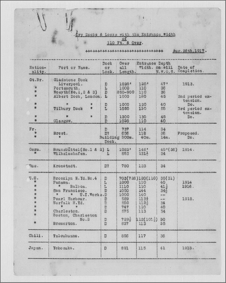
The primary naval base, Portsmouth sported the 258m long ‘C’ and ‘D’ basins. If the caissons were in the extended position at both ends this could be boosted to 281m but this required a preparation work of 3 weeks meaning that this was more of a paper option than a practical solution.
The overall shortage of suitable docks was eased a bit by the ex-German Kiel No.8 floating dock which was acquired from the Germans after the war and the new owners lengthened it. This way Malta had a 293 X 42.6 X 11.8 m[7] dock with a lifting capacity of 65.000 tons, more than enough for the intended ships. Still, the deciding factor regarding the size of any new ship would be the docks available at Rosyth and Portsmouth as these were the intended home ports.
The first battleship-battlecruiser pair – October 1920
It is to be noted here that the new naming sequence was introduced in Oct 1920 with the battleship plans getting letters in sequence from L to Z while battlecruisers got an indicator in reverse sequence from K towards A. The number next to the letter indicated the number of barrels per turret (2 = two gun turret, 3 = three gun turret). Smaller changes and differences got an extra letter written in non-caps at the end, like H3c.
According to the original order of the 1920-21 fiscal year design work proceeded with a pair of battleship and battlecruiser designs.
Since it is far from being practical to exceed the size of available docks the designers tried to adhere to this limit as much as they could. Unfortunately the 260 X 33 X 12m dimensions forced upon them meant that to fit in everything into this volume entailed a very high block coefficient – in other words the ship would be very fat and brick-like. Originally they started playing with a longer and broader hull which allowed for much finer hull lines that in turn resulted in much better hydrodynamic properties on top of nicer aesthetics. It allowed for an extra half knot speed and better handling while requiring the same propulsive power.
In the background though feverish research work was going on in the Navy’s hydrodynamics research basin located in Haslar. They were working on a new solution called the transom stern. It was suspected for quite some time by DNC and other constructors that the very tip of the stern behind the rudder post barely immersed into the water and as such had a very minimal impact on the hull’s performance cutting through water. The model basin tests justified this idea path as even the wildest, 10 meter shortening of the stern had only minimal impact on resistance. A cut right aft the rudder was even better, practically meaning no difference compared to the full length hull with a 1-2% increase in resistance at low and medium speeds but with an actual reduction of it at high speeds! So in essence the solution gained a slight speed advantage with everything else being the same over the full hull length models. This development was so well liked by the designers that except for one design all the other variants in the below series adapted this as they could reduce the waterline length significantly without any significant drawbacks (ship endurance suffered minimally due to a little more power being needed for cruising speeds).
Armament was still considered to be optimal with the 18″/45 Mark II guns laid out in four two gun turrets, equally distributed fore and aft in superfiring turret pairs – that is from a tactical point of view. From a shipbuilding standpoint which accounted for space, weight and firepower the three gun turret offered undisputed advantages: using three of those would yield an extra gun while saving 1000 tons in direct weight which could be used to strengthen the armor.
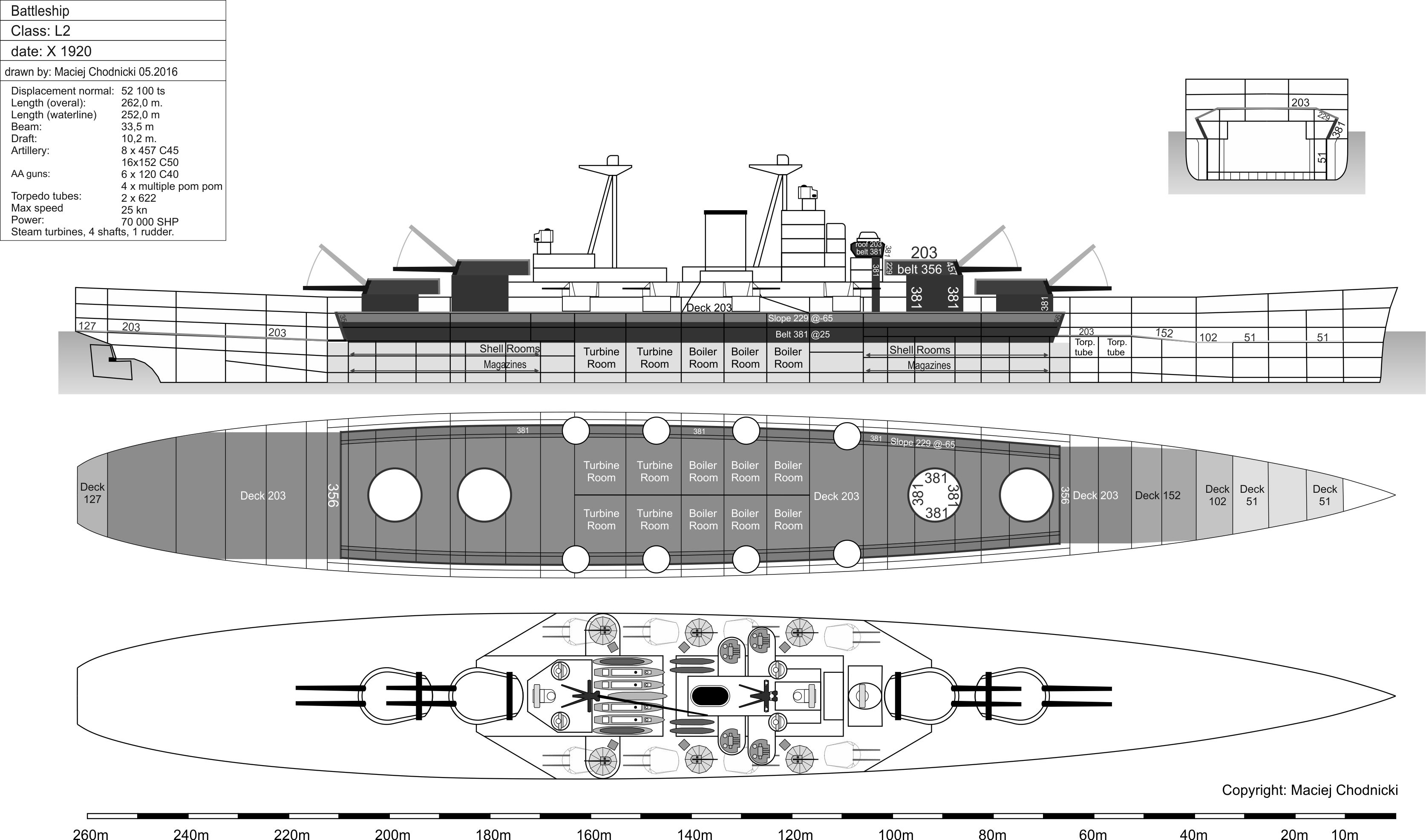
From this train of thought they came up with battleships ‘L2’ and ‘L3’ along battlecruisers ‘K2’ and ‘K3’. The battleships had a 262 X 33,5m hull while the faster siblings were a bit longer and narrower at 270 X 33 meters.
The versions with ‘2’ had the classic turret layout described above with 300° arcs for all four turrets, offering very good distribution and field of fire.
The versions with ‘3’ had nine guns with 2 three gun turrets on the foredeck superfiring above each other with a third turret sitting aft of the superstructure facing aft. The larger three gun turrets had to be compensated for with reduced superstructure length to offer similar firing arcs and also not to push the very heavy barbettes and structures too far apart as that would result in excessive bending stresses on the hull. Ammunition was set at 100 rounds per gun for the BBs and 80 rpg for the BCs.
Secondary batter was as per the requirements set by the Admirals Staff with sixteen 152mm quick firing guns installed in 8 twin turrets equally distributed on the two sides of the superstructure for the BBs and in a 3 facing forward, 1 aft pattern for the BCs, all on the main deck level.

The battlecruisers had two huge funnels, same size as HOOD had since the machinery used the same layout and power output as the predecessor’s. The battleships made use of one funnel only since they had half the machinery with 70.000 SHP. The former ships had 4 screws while the latter only 2 but all four variants sported 3 boiler rooms – obviously in case of the faster battlecruisers those were more voluminous, allowing for a top speed of 29 knots instead of the slower ships’ 24-25 knots.
The overall shape of the superstructure and the hull layout was quite similar for all four and these designs introduced the transom stern. The stem on the other hand was still reminiscent of HOOD’s shape with a bit less flair maybe while the block shaped, bastion-like, fully enclosed main tower and bridge was also new. The heavily armored conning tower made a return. The new tower structure was needed due to the ever increasing weight and space needs of equipment encroaching on the masts that had limited capacity in both measures to begin with. Also the tower structure could raise the directors and main range finders much higher, up to 28m above the water line. Though the space requirement was mainly due to the increased numbers and size of directors, a roomy bridge and conning station high up was also a desirable feature that this solution delivered. For signalling and for radio antennae purposes two classic tripod masts complemented the tower structure, one right behind it, the other, main mast at the back end of the base superstructure. There was only the main conning tower, no aft or secondary unit was provided for. The rest of the ship’s superstructure followed fairly classic lines with boat stowage between the main mast and the funnel(s) and searchlights, deck fittings etc. distributed as per current practice.
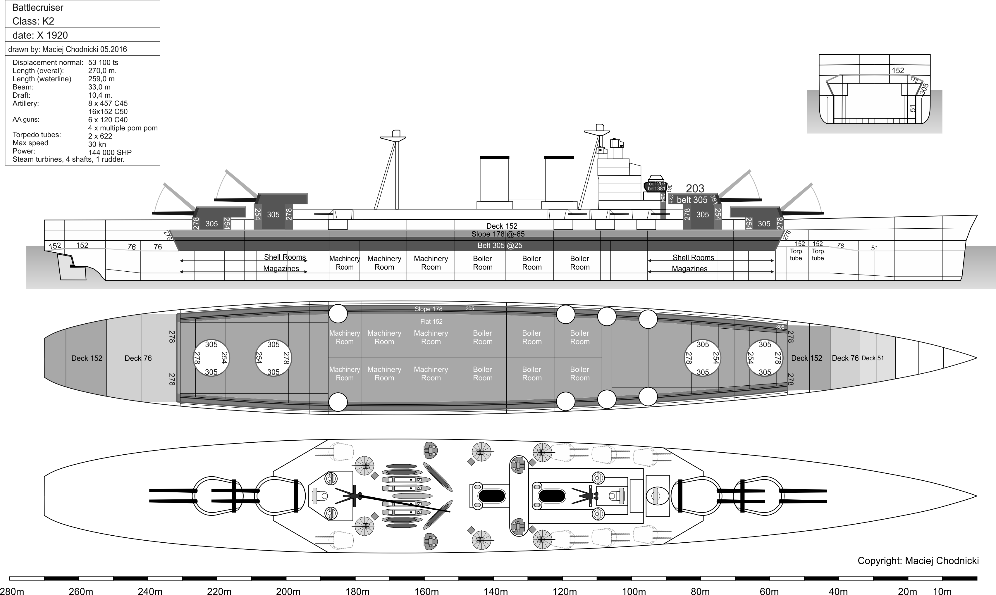
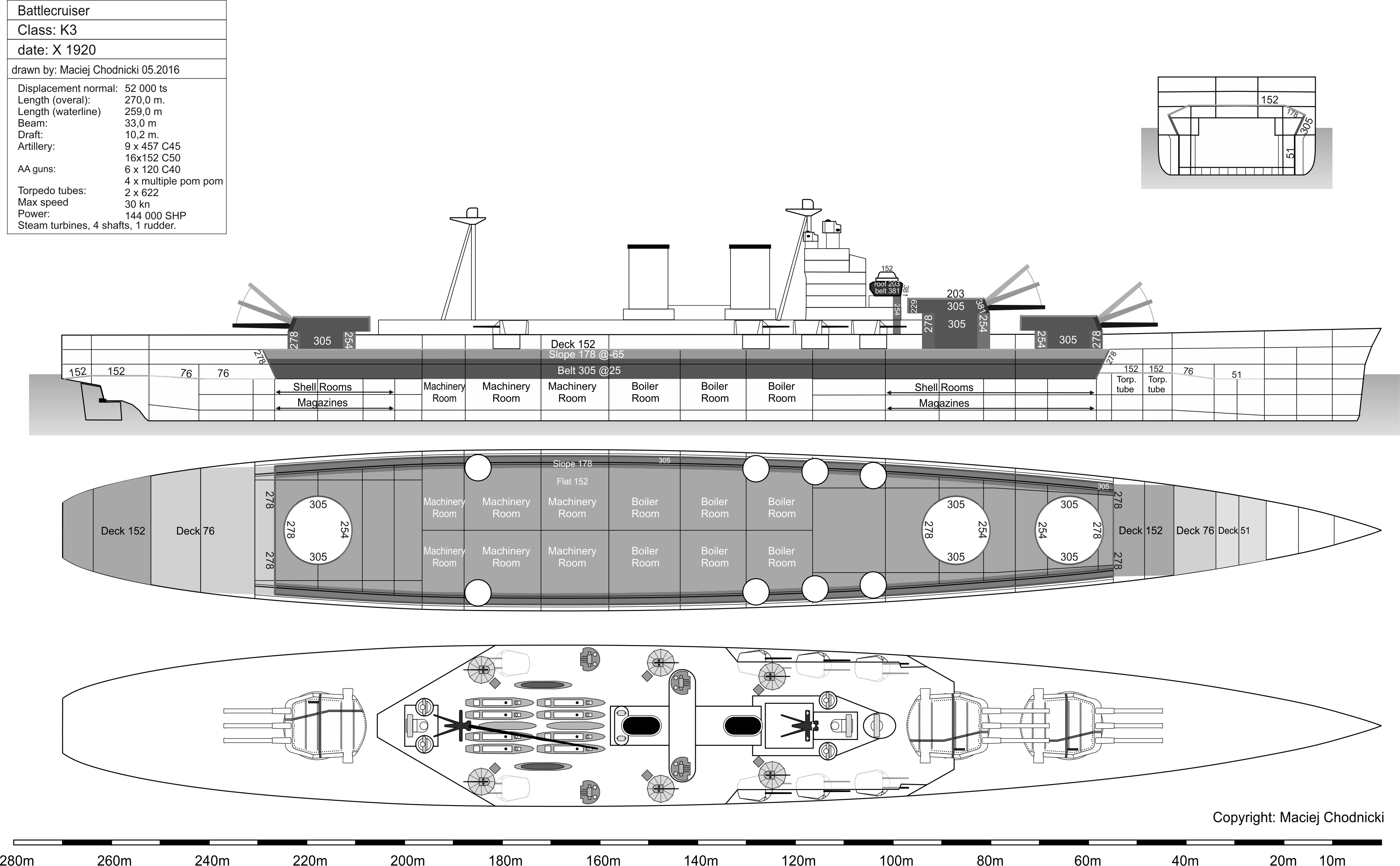
The hulls on the other hand were anything but classic. As mentioned the transom stern made it’s debut together with a flush deck sheer line that increased slightly going forward in order to keep freeboard constant. What was radically changed however lay beneath the surface in the form of a new armor layout, following the all-or-nothing principle with some extras. The main belt was fitted internally as a structural member, as sort of an inner shell. At it’s top edge it lay approx. 1m behind the outer shell and it extended for 2.95m above and 2m below the waterline. What is really staggering is the 25° angle from vertical at which the belt was fitted at (necessitating the internal mounting) and it’s thickness reached 381mm for the battleships and 305mm for the battlecruisers. In effective protection terms this meant 450mm and 360mm thicknesses respectively. Taking into account all existing foreign and domestic warships these values exceeded any of them, by far, especially domestic ships could not even come close to these values. The closest so far was the ‘R’ class battleships’ 330mm belt but that was only on it’s main strake and it was not inclined so effective thicknesses were much less. Among battlecruisers HOOD had a similar belt but it’s inclination was only about 1/3 of the ‘K’ designs and the 305mm parts of the belt reached to less height on the side.
Of course there is an underside for everything in design trade-offs, here the price to be paid came from the vulnerability of the completely unprotected outer shell. Even small fragments or HE shells could open up the hull causing flooding. Exactly to counter this threat Goodall and his team made careful calculations to keep the size of space between the belt and outer shell at the minimum which would not endanger stability even if fully flooded.
Length of the main belt and deck varied for all 4 designs, it started at the leading edge of the foremost ‘A’ barbette and ended slightly aft of the aftermost ‘X’ or ‘Y’ barbette’s aft edge. The transverse closing bulkheads were 356mm thick for the BBs and 278mm for the BCs and all were canted outward at approx. 45° to offer extra resistance. The main armored deck sat slightly above the upper edge of the belt one deck level below the main structural deck. It’s sides were slightly sloping downwards to connect to the upper edges of the belt. The main structural deck was also armored at a thickness of 37mm and there was an additional 25mm splinter deck just below the main armored deck but this only covered the magazines. Where we get really massive values is the main armored deck, it’s flat parts came in at 203mm while the 65° to the vertical slide slopes boasted a strength of 229mm. This reversion from a completely flat deck to one with sloping sides was mandated by the very steeply inclined belt armor – to keep armored volume constant and to be able to fit the boilers completely below armor protection the deck had to be raised in the middle to gain back what was lost in the ship’s bottoms and sides. To offer the same protective value the slopes were made exactly 25,4mm (1 inch) thicker than the flat parts but strangely enough the difference is always the same regardless of the main flat part’s thickness which differed for the BCs and BBs. The flat part of the main deck continually thinned down to 127mm towards the stern and to 51mm towards the bow; for the battlecruiser sisters the flat main decks were at 152mm thickness with 178mm slopes (again 25.4mm diff.).
The gun turrets themselves were finally massively protected (in contrast to British practice so far) with 457mm face plates, 356mm sides and 203mm roofs for the slower pair of designs and 381/305/203mm values respectively for the faster variants. Barbettes were equally massive with 381mm tapering downwards to 305mm for the ‘L’ series and 305mm to 254mm for the ‘K’ series ships. At least one source indicates the high probability that a downward coned barbette design would have been used for the battlecrsuiers to compensate the somewhat lower values. Even accounting for this the overall protection of the battlecruisers was designed against the 381mm weapons, only the thicknesses in the battleship design are fully satisfactory in resisting it’s own 457mm projectiles – which shows the tremendous power of the 18″/45 Mark II.
The total armor weight for each design as follows (HMS HOOD included for comparison):
L2: 52.100 tons displacement / 18.850 tons of armor
L3: 51.100t / 17.800t
K2: 53.100t / 17.310t
K3: 52.000t / 16.060
HOOD: 41.500t / 13.650t
Again, it clearly shows that even though the HOOD was considered well protected only 2-3 years ago the weight of armor rose almost 40% (‘L2’) while total displacement went up 25% and quite a lot of that difference was spent on upping the armament considerably.
The sub-surface threats had to defeat a 2,5 m deep double bottom or a 51mm thick armored holding bulkhead to penetrate into the ship – the system should withstand the explosion of a 340 kg warhead, as defined in the requirements of the Admirals Staff. The holding bulkhead was fitted approx. 4,5m distant from the outer shell. Part of the protection were the integrated bulges that were longitudinally divided into outer void and inner liquid loaded compartments.
Despite their monstrous size all four of these variants could fit the docks at Portsmouth and Rosyth (just barely) and could pass the locks of the Panama-canal, however their draft was too deep to navigate the Suez-canal without offloading all ammunition and most of their liquid/fuel loads which is not a practical thing to do in case of war.
This first series of plans was a huge step toward the concept of a new fast battleship, still they did not satisfy the design team entirely as they were oversized and the battlecruisers – which were for the time being of the primary importance – proved to be too slow at 29 knots in contrast to the 33,5 knot LEXINGTONs. What’s more the Japanese AMAGI class ships were rated at 31-32 knots as well, though there is no information about how much of this was known to the British at this point in time. What is even worse though is that the internal benchmark, the HOOD was also faster at 31,5 knots…
Critics did not spare the battleship designs either, where the main shortcoming was held to be the relatively short belt armor (though international competition was not much better in this regard).
Due to these points the ‘L’ and ‘K’ series stayed in the preliminary stage and fresh designs were looked at, first for the high priority battlecruisers as the orders have changed to 4 such units from the previous 3 BB-1 BC constellation.
J3, I3, H3a, H3b, H3c – battlecruisers all-in; Nov.-Dec. 1920
The takeaway message from the previous series was the economy offered by the triple gun turret in balancing the weight(speed)/firepower/protection trio. The designers recognized this early on and successive designs discarded the two gun turret with only one exception – this was especially important for battlecruiser designs where high speeds could be attained with weights kept to a minimum.
Interestingly enough the first new design, ‘J3’ took quite a retrograde step: it was one last and final attempt to utilize the HOOD hull shape. In essence they renewed the May 1918 redesign of the famous ship where three triple 457mm turrets were fitted, but this time these gave way to a hypothetical 15″/50 weapon, fitted again in three triples. The belt armor moved back to the outer shell but it’s inclination was kept at 18-20° and the completely flat main armor deck set atop the upper edge of this belt. The deck’s thickness was cut to 102mm from ‘K’s 152mm though. Machinery was not changed much, a rating of 150.000 SHP was taken as reference based on experience with the trial runs of HOOD and this yielded a calculated speed of 32 knots without the transom stern. The modern looking, bastion like tower structure and the secondary battery layout were taken over from design ‘K3’.
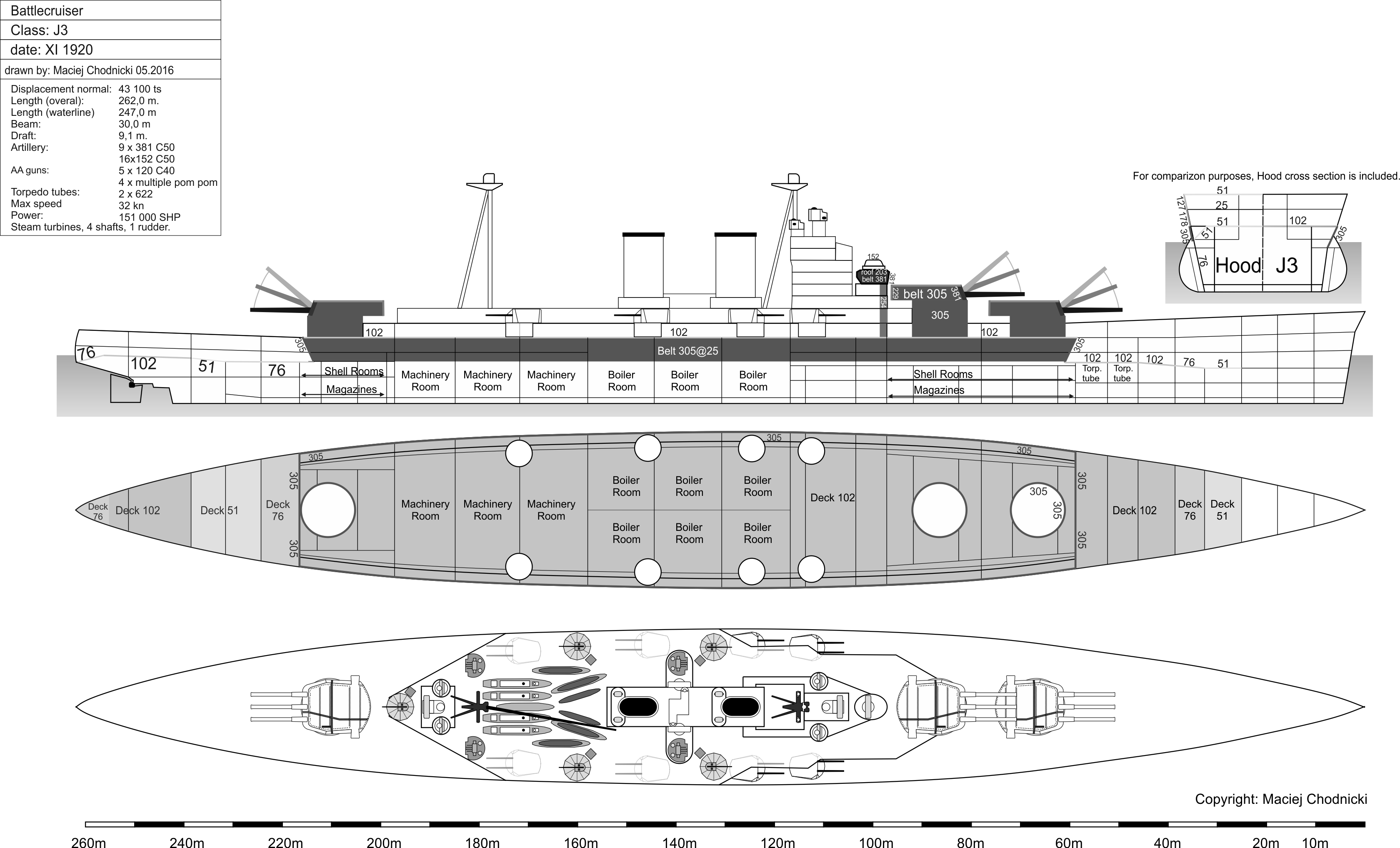
This design however gave up too much from the armor protection, at only 43.100tons it carried 12.780tons of armor, a value even lower than HOOD herself and it’s top speed was still a good 1,5 knots short of the bleeding edge. No matter what, getting into very high speed territory demanded an extreme price to be paid in other ship qualities as the USN designers learnt it the hard way during the LEXINGTON design (see there).
In addition to this DNC realized that the huge funnels and air intakes associated with the battlecruisers acted as similar sized continuity gaps in the horizontal protection. In case of enemy fire from forward bearings at short ranges (where the impact angles are shallow) there was a good chance for a shell to easily pass through these openings (even if they are protected by armor gratings) and end up in the after magazines. To mitigate this risk D’Eyncourt came up with the idea in late September or early October of moving the machinery spaces and the related openings from the middle part of the ship into the after portion and putting the after turret(s) in their place. This meant that the risk was reduced to hits coming from directly aft – not a likely scenario. Again as the saying goes ‘no pain – no gain’: the superstructure had to be moved as well with the uptakes so the after part of the ship basically blocked all aft bearings for the main battery this way. However experience from the past war showed that the dreadnoughts almost never used their main batteries on aft bearings[8]. The DNC killed two (or 6) birds with one stone implementing this brilliant, if risky solution:
- it reduced the probability of magazine hits through armored deck openings to almost zero thanks to the very narrow blind spot from aft
- the funnels were removed this way from the main tower structure, solving the serious smoke – fire controls interference issues which was a recurring problem in the earlier dreadnought classes
- the space formerly occupied by machinery now could be used by magazines which in turn allowed for the concentration of armor protection even further: it was enough to massively armor the relatively small portion of the hull over the magazines which could be compressed in length thanks to their new, very broad location in the middle of the hull
- this new location also meant that bending stresses got reduced to the minimum as the extremely heavy weight barbettes and turrets did not press down on the two far ends of the hull where the hull strength was further reduced due to the barbette cutouts; also the center of gravity was more closer to the middle of the hull making handling easier
- the machinery on the other hand could be spread out in length as the requirement to keep the barbettes closest to the middle part was now gone – the longer machinery spaces allowed for more redundancy and less impact if one space got damaged or flooded
- it was only the icing on the cake that the magazines got the deepest possible torpedo protection in the middle part instead of being stuffed into the ‘corners’ where the TDS was the weakest due to the fine hull lines
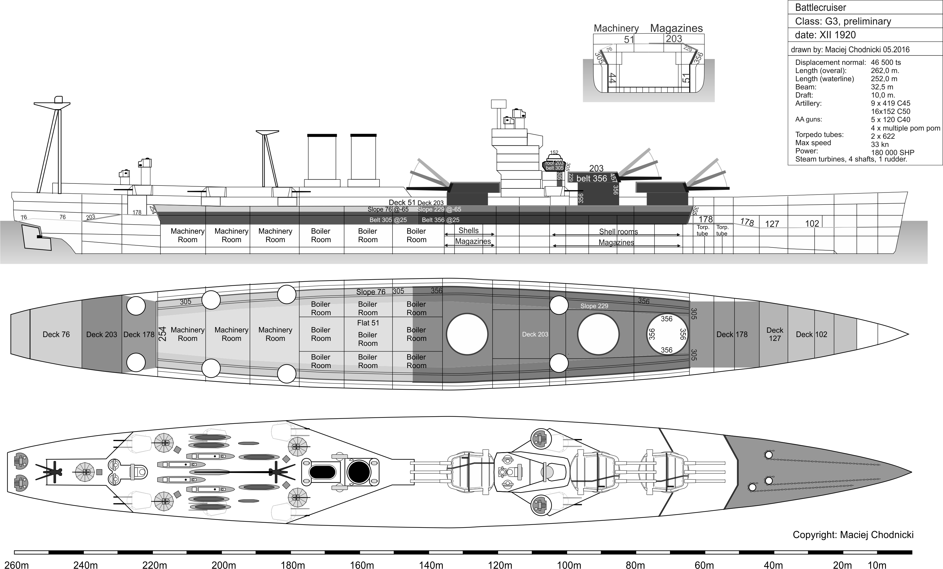
From the above train of thought descended in November 1920 the design ‘I3’ in battlecruiser form and ‘M3’ in battleship form (this one to be discussed later).
The’ I3′ was the exact opposite of what the ‘J3’ tried to accomplish. The designers pulled out all stops, realizing and accepting that very high speeds can be attained only by further increasing propulsive power and ship length. Thanks to this a true monster came to be which would have been an overwhelming opponent for even the LEXINGTONs and AMAGIs. The 282m long monstrosity was the longest (but not the heaviest!) British capital ship ever designed up until the 1944-45 redesign of the LION class battleships.
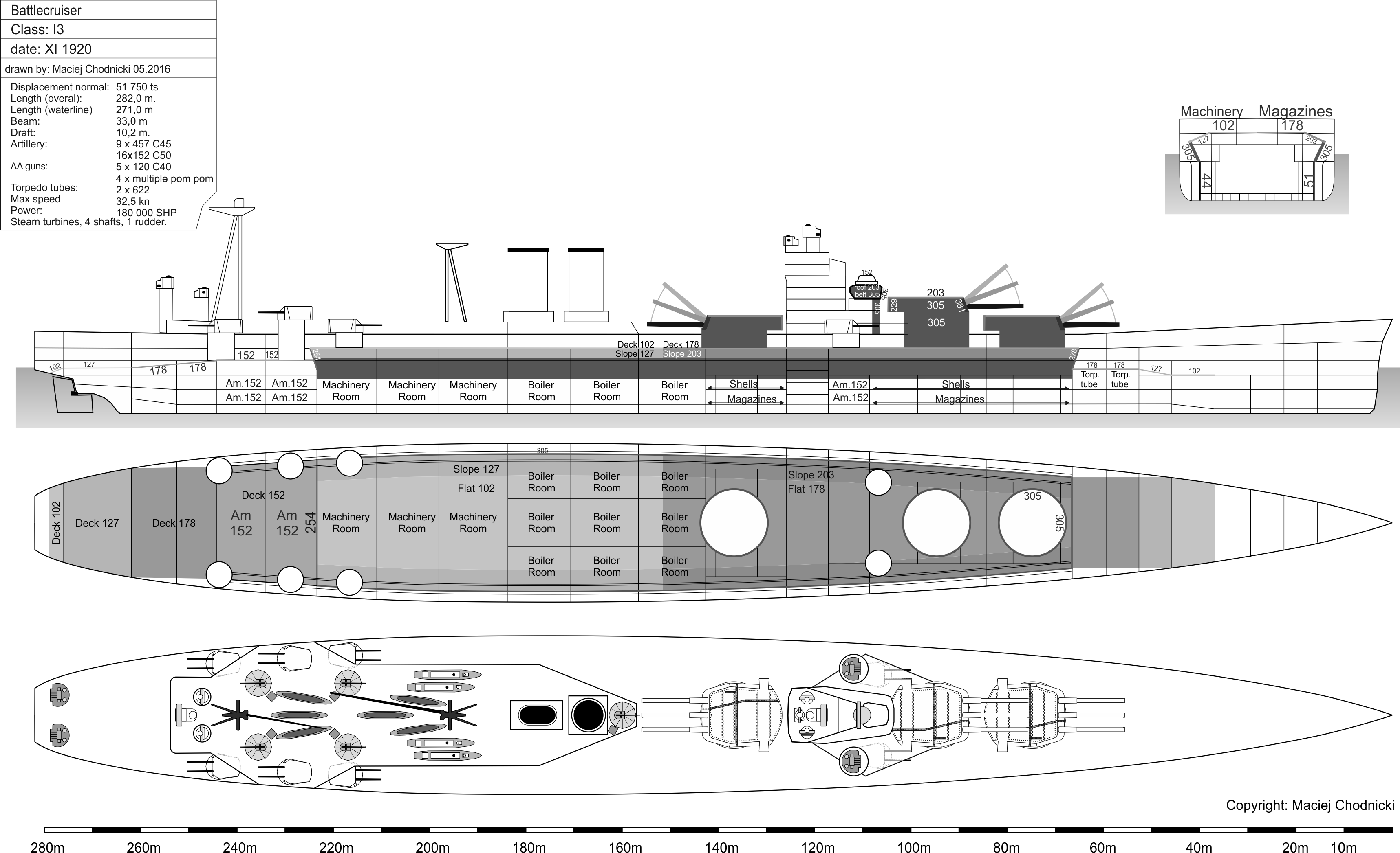
Compared to ‘K3’ the new arrangement invented by the DNC bought 3,5 knots extra speed while keeping the same armament and the armor was even increased over the magazines to 203mm/178mm from the previous 178mm/152mm; finally the barbettes, which were the Achilles-heel of ‘K3’, got a uniform thickness of 305mm – all while the total displacement decreased by 250 tons!
It was in the ‘I3’ design first that the void between the inclined belt armor and the outer layer of the hull was planned to be filled with small diameter metal tubes (just like in HOOD) in order to boost the strength of the TDS and to act as a decapping material against APC shells.
The increased hull size could take on a massive 180.000 SHP powerplant that transmitted power through 4 shafts. This was the maximum possible power with current propeller designs utilizing 4 shafts – more shafts were out of question since they required a much broader hull. This amount of power made it possible to drive this beast at 32.5 knots, an amazing number given the armament and armor carried by the ship.
The bastion shaped tower structure and the heavy conning tower got inherited from ‘K3’, just like the transom stern and the flush deck hull with the internally mounted, sloped (25°) belt armor. The tower structure got it’s place between the front two and the aft (middle) three gun turrets. The aft superstructure’s forward part got a wedge shape in order to maximize the firing angles on aft bearings: approximately a 40° wide slice was still blocked by it and the huge diameter funnels sitting right at the tip of the wedge. The aft facing tripod mainmast was placed behind the funnels and a second, auxiliary tripod mast facing forward got it’s place right at the aft end of the aft superstructure.
Secondary armament also reflected ‘K3′, the distribution of the turrets got changed however as the new layout necessitated their relocation. One pair got it’s place next to the tower structure while three pairs were moved aft with the middle pair superfiring over the forward and aft facing ones. This layout can be criticized as sub-optimal, as the distribution of firepower left the most contested forward angles with less guns while the two aftermost pairs’ ammunition hoists were not even covered by the belt armor, making them a potential weakspot.
It is not too difficult to imagine why the otherwise perfectly fitting design variant was discarded: thanks to it’s gigantic length only the Gladstone dock could have taken on this ship and this was a decisive factor.
How could they shorten the ship radically while keeping most of it’s qualities? Well, the first answer came in December 1920 and it was to reduce the main battery to 6 barrels with sacrificing one turret but otherwise building on the successful if oversized ‘I3’. This train of thought yielded the ‘H3’ series that contained 3 sub-variants.
The ‘H3a’ was probably the most elegant yet quite probably most practical of the three: the middle turret located behind the tower structure and it’s magazine was simply cut out. The weight reduction was a phenomenal 7.000 tons, and in reality the gain was even bigger as the armor got some beefing here and there. What was more important is that the waterline length shrunk by 20 meters.

The 180.000 SHP propulsion plant and it’s arrangement was taken over from ‘I3’ and it’s armor protection remained the same with a 102mm deck and 305mm belt surrounding it. Magazine protection on the other hand could be increased to the level of the ‘L’ series battleships, meaning full protection against 457mm caliber hits. Barbettes increased to 356mm, only 25,4mm short of ‘L’, the rest of the values were the same as there (203mm/229mm deck).
This was then the first design in the series that used split thickness protection on the belt as well as on the main armored decks, which resulted in a fairly well balanced design with one major weakness: the shortcoming of ‘a’ was the 60°wide aft blind-spot where no main guns could bear.
Secondary battery mirrored that of the ‘K’ designs, now that the middle turret was gone the space could be reused for the secondaries again.
Thanks to the much reduced size and weight top speed further increased by 1 knot to the desired 33,5 knots, while still fitting the relevant drydocks.
The ‘H3b’ on the other hand surrendered it’s foremost, ‘A’ turret together with it’s barbette and supporting hull part. The former ‘B’ turret remained in it’s original elevated position in order to keep it’s somewhat better firing angles on aft bearings, and what’s more they even elevated the mid turret to the same level, for the very same reason. This meant that the aft blind arcs got reduced to a mere 20° and at the same time the main battery did not interfere with the secondary guns which inherited the ‘I3’ layout. Armor was exactly the same as variant ‘a’ but the higher barbettes needed a bit wider hull and this reduced the speed to 33.25 knots.

Finally ‘H3c’ wanted to address the negative aspect’s of ‘b’s high barbettes so here the main turrets were lowered one level to the main deck which in turn reduced the CT and main control tower height as well. This also reduced armor weights and allowed for a narrower hull with some top speed gained: as high as 33.75 knots. The pain to the gain here was aft firing angles for the middle turret and secondary battery distribution: in this case all quick firing armament had to be placed aft and in this case 3 of the 4 pairs were without armor coverage on their ammo handling rooms.

On paper the ‘H’ series appeared to be really attractive, especially variant ‘a’ as they satisfied the requirements both in size, armor and speed. Gunnery people however frowned at these designs as they did not like the low amount of main guns: 6 gun broadsides were the bare minimum for effective ranging salvos. The real issue for them was the concentration of armament into two turrets only that meant in case of battle damage or mechanical failure half of the armament got disabled, leaving the huge ship massively impotent.
First version of G3
Approximately concurrent with the ‘H’ series, there was an alternative ‘G3’ design being worked on in Dec 1920. Also based on the ‘I3’ here the designers reduced the caliber of the main battery instead the number of turrets. For this they used a gun which was also in the development phase only, the 16.5″/45 Mark I [9], basically this shrunk the ‘I3’ design and layout to the size of the ‘H’ series (262m length on 46.500 tons). Armor was almost exactly similar to the ‘H’ designs, with the addition 1300 tons reduction coming largely from the deck above machinery which went from 102/127mm to 51/76mm – here they still kept the 25.4mm difference between flat and sloped part, though arguably here one inch of difference meant a lot more than for example with the ‘L’s 203 vs 229mm decks.
Thanks to the smaller size of the main battery turrets the funnels and after superstructure offered less of an obstruction so the firing arc improved 10 degrees down to 30°only.
The machinery was unchanged with the 180.000 SHP plant capable to drive this hull at 33 knots.
Predictably the Admiralty choose this design for further refinement in January 1921.
Battleships M2, M3
Approximately concurrent to the ‘I3’ there was also a battleship design sketched up, but much less effort went into that compared to the battlecruiser.
The ‘M3’ was drawn up in November 1920 as the battleship counterpart of ‘I3’. Since this was a battleship design focus shifted from high speed to heavy protection, so the required 23,5 knots speed (probably to match the QEs) could be met with less than a third of the battlecruiser powerplant, a mere 56.000 SHP sufficed. This actually is quite remarkable and justifies the efficiency of the transom stern, as the QE class units required 75.000 SHP for a designed speed of 24,5 knots (actual 24 knots) on a 13.000 tons lower displacement! The less powerful machinery took up a proportionately smaller space as well as needed one fairly small funnel only. Furthermore this amount of power could be transmitted through two shafts only so the two propellers could be made larger diameter which offered better efficiency at cruising speeds and could be spaced further out from the center line which offered better maneuverability in case of damage to the single large rudder.
What is unique to this design so far in this series (and survived even to the actually built NELSONs) was the reversed order of machinery: the boilers were moved aft of the turbines! This arrangement offered several advantages while needed only minimal compromises. First of all the hot steam lines did not have to be routed around or close to the middle barbette. In earlier dreadnoughts this was a major issue as the hot steam lines heated the massive steel structure that in turn heated the cordite charges and that reduced ballistic performance which led to uneven gunnery performance for the middle turrets. Furthermore with this layout even that single small funnel could be moved further aft, reducing any obstruction to the guns in the center and reducing the blind spot to 30°from the ‘I3”s 40°. The only real drawback associated to the boilers aft was that the turbine shafts had to be routed below/through the boiler rooms – this was an additional reason for using only two shafts.
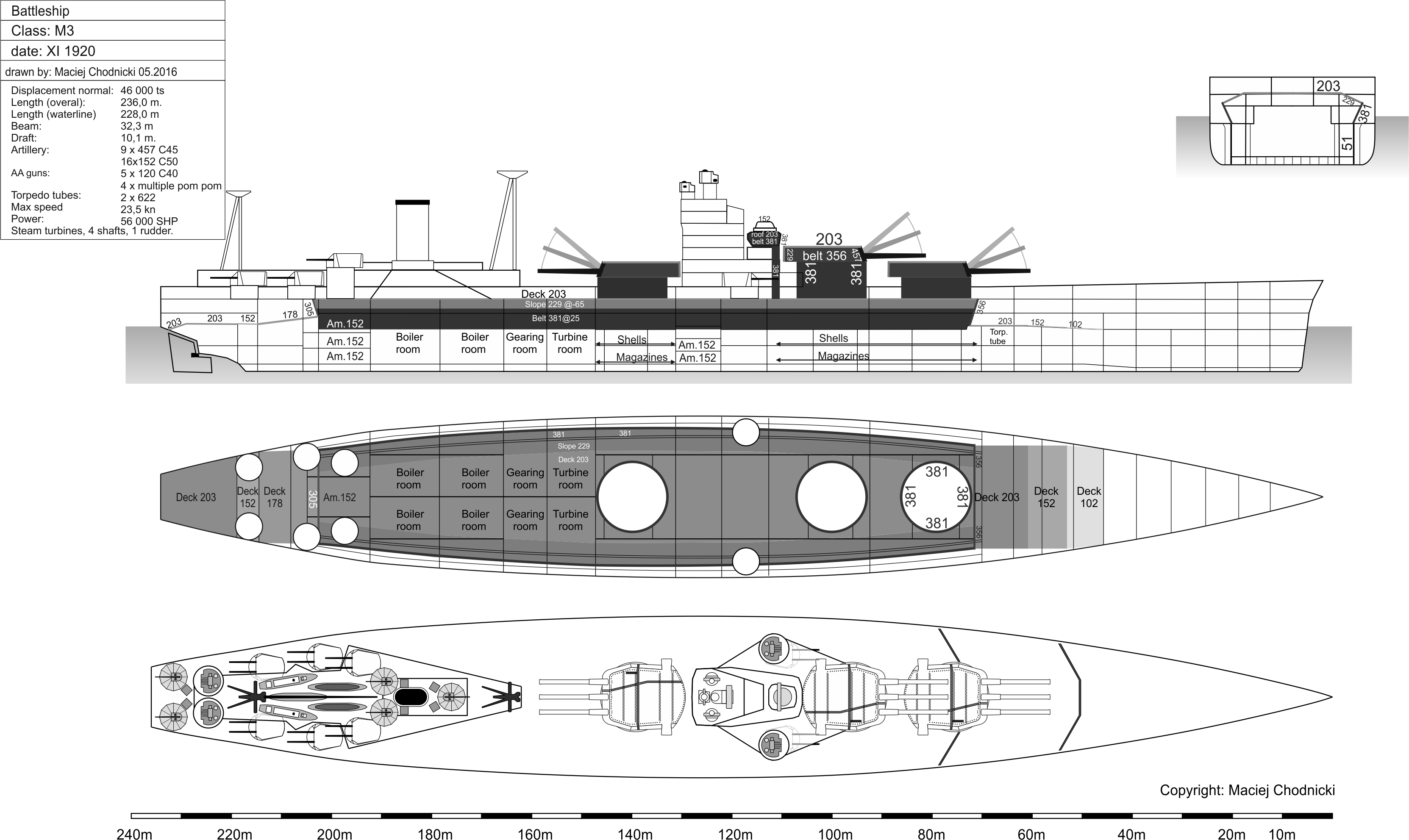
As the ratio of magazines to machinery spaces moved seriously in favor of the former there was no point in using a split thickness belt and deck armor scheme, so the whole length got the same protection values. There was still a 25° to the vertical sloped internal belt having a thickness of 381mm with a 203/229mm sloped-side deck sitting on top. Both turrets and barbettes got full protection versus 457mm AP shells.
Secondary battery layout mirrored that of ‘I3’
Torpedo protection and double bottom remained the same as ‘L’ series.
Thanks to the new setup compared to the previous battleship study ‘L’ they managed to carry the same armament and armor on 5000 tons less displacement while further enjoying the other benefits listed for ‘I3’.
Being a battleship design the Admirals Staff stubbornly clung onto the idea of using two-gun turrets in a classic 4 X 2 arrangement. Goodall and Attwood prepared a variant to satisfy that need, named M2, where they used two-gun turrets with 8 guns in total, with the tower structure in between the pairs of turrets. The M2 was 2750tons heavier compared to M3 while sacrificing 1 gun – and all it gained was somewhat better distribution of the armament. It left no question that M3 was the way to go.
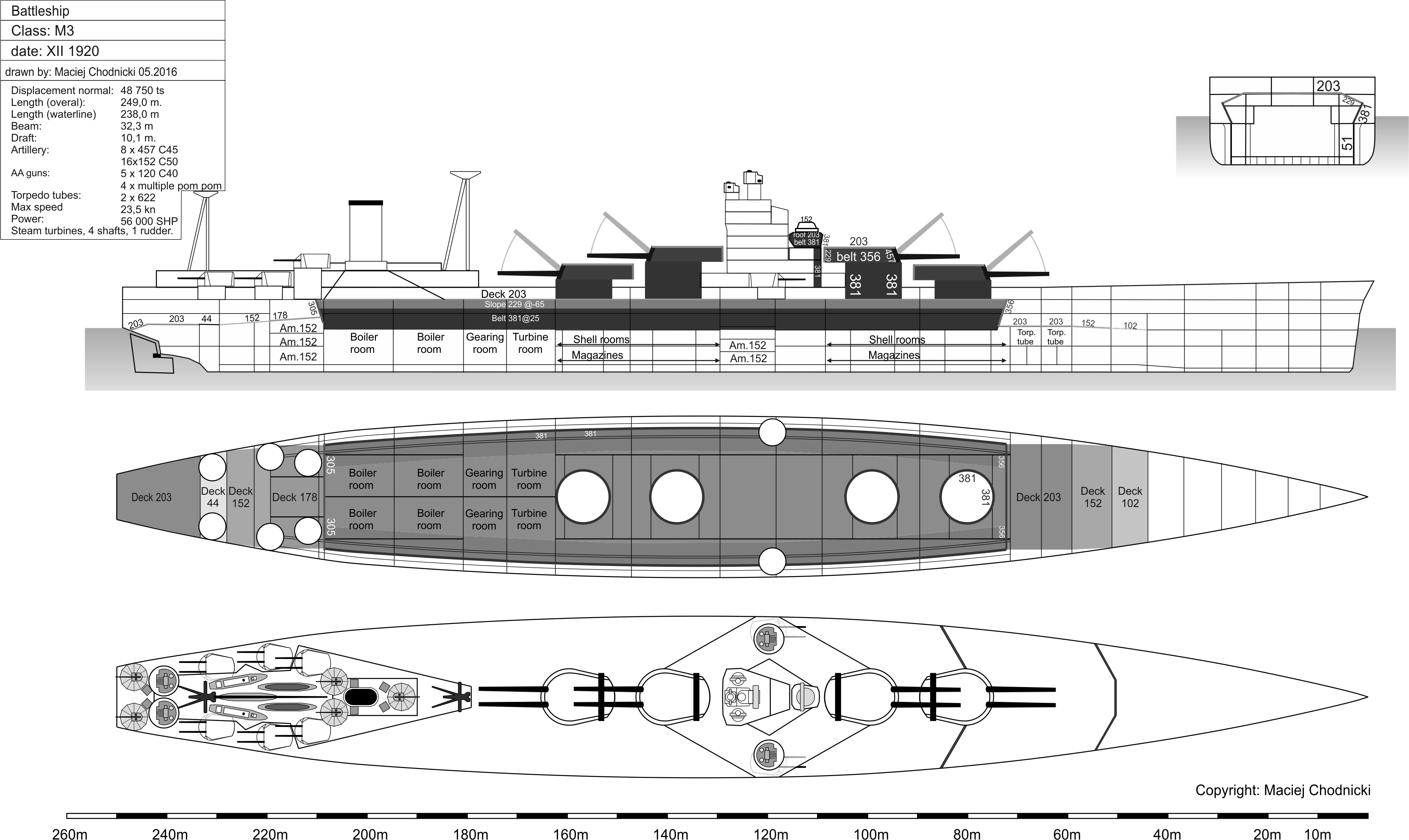
There were still two critics against this preliminary design: the sloped bulkheads and the high number of personnel required to service the manual loading 152mm quick firing battery. The DNC suggested using triple turrets for them and making them utilize an ammo elevator like the big guns did. However due to the weight of the 18 gun battery this solution might not have been much better overall and it was not worked out in detail.
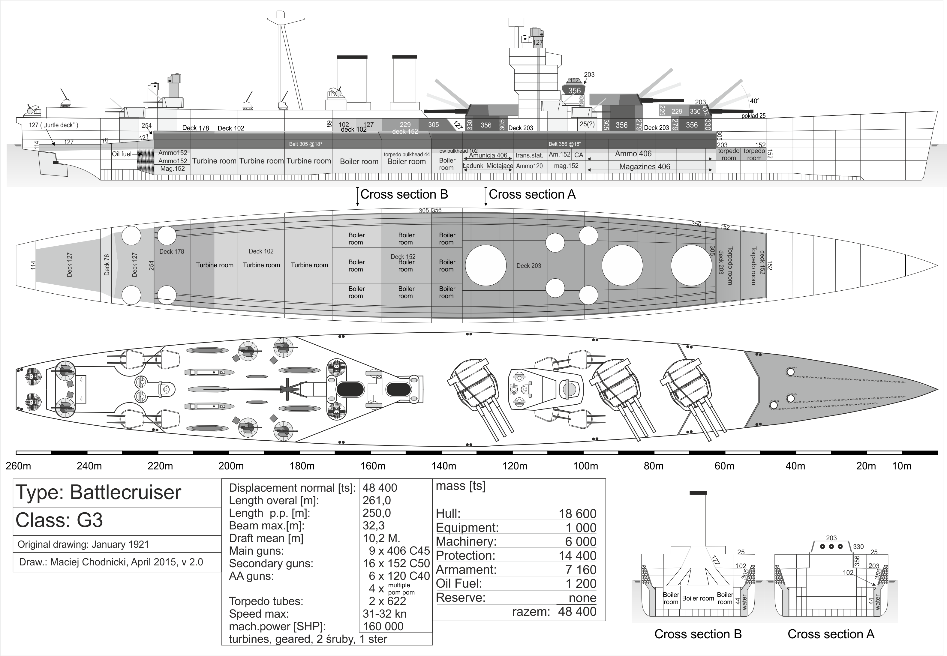
The most well-known: G3’s detailed variant, Jan-Aug 1921
At the end of 1920 the Third Sea Lord held a meeting where the G3 and M3 designs were downselected from the above designs as worthy for further development.
The G3 promised a lot as it was in it’s preliminary form though it still had some obvious shortcomings that had to be ironed out, such as the relative thin deck armor over machinery (51mm only). The DNC therefore asked for new plans where this was thickened to 76 then to 102mm. This meant an extra 1125 tons weight which was compensated for in several steps:
- the secondary battery was reduced from 8 to 6 twin turrets (later restored) – 100ts gained
- 30cm reduction in height of the 356mm forward part of the belt that covered the magazines – 115ts gained
- the armored deck over the same area was changed to almost completely flat with a uniform 203mm thicknes [10] – 125ts gained
- with the slight reduction of turret armor they spared another 75 tons
Altogether 710 tons was cut which still left a total displacement of 47.500 tons. Other changes were made to the armor, for example the slope of the belt was reduced to a much less demanding 18° as some concerns surfaced regarding the stability in riddled conditions together with a 25°belt [11] – with the latter the space between belt and outer shell was simply too big and could take on too much water in case of damage. To further reduce this risk the space was filled with small diameter metal tubes just as in HOOD. Probably shell deflection reasons the front and aft transverse bulkheads were made completely upright from the previous canted positions.
Furthermore the question arose if the really high, 33+ knots speed was justified, especially in contrast to the huge difference in protection compared to LEXINGTON which generated this requirement in the first place. Thanks to Goodall’s work with the USN’s C&R’s preliminary Design Branch the British designers had a pretty good idea about the LEXINGTONs. In the end the Staff decided that an optimized machinery and reduced weight was well worth the loss of half-one knot. The former 18 boilers could be changed to 20 individually smaller and more modern units. This way power dipped to 160.000 SHP that resulted in a top speed of 32 knots. Truth to be told the hull contour had to be changed somewhat to make space for the newly implemented reduction gearing as well (which massively increased fuel economy at cruising speeds) and the new shape had somewhat increased resistance that was part of the speed reduction.
In order to keep weights in check it was the main armament that got changed: from the 16.5″/45 Mark I they went to the 16″/45 Mark I which was a fairly logical step as the latter gun was already under construction unlike it’s bigger brother. This also reduced weight even further so the 16 gun secondary armament and the 30cm higher main belt could be restored. Turret ‘X’, the one behind the tower structure got a firing arc of 60+10° out of a 90° slice on aft bearings. The extra 10°was marked separately as this was only to be used under war conditions as the blast could damage the funnels due to the proximity of the muzzles.
The arrangement of the 152mm battery was also changed: the preliminary design had only one pair of these turrets in a really useful place, on the two sides of the tower structure, the rest were grouped on the stern but below the gallery deck, almost like casemate guns. This was a major issue as in case of damage debris from the gallery deck could easily block the turrets and placing them in recesses also negated other advantages stemming from the turreted setup, for example it reduced firing arc severely. Therefore two of the after pair was relocated right aft of the forward pair next to the tower, in a superfiring position, facing forward. This way 4 turrets could fire on the most important forward bearings with a barrel elevation of 40° if necessary (meaning they could use the maximum theoretical range of these guns). The other two pairs were set up in a similar manner on the stern, facing aft with the lower pair sitting on the main deck and the other above it on the gallery deck. They were moved within the after armored belt’s protected area. Going from bow to stern the following firing angles were available: first pair: 90° forward/ 60° aft ; second: 70°/ 80° ; third: 70°/90°; fourth: 60°/ 90°. To supplement this they somewhat redesigned the shape of the aft superstructure as well as the number and arrangement of the tripod mast with only one main mast behind the funnels supported by a tiny pole mast at the very tip of the stern.
In April 1921 the torpedo armament changed as well with the former 533mm tubes giving way to the brand new 622mm ones in order to comply with the Admirals Staff new wishes that wanted the new, oxygen driven, 447kg warheaded subsurfaces weapons. In June they even added an oxygen compressor to the list of wanted items. The DNC was unenthusiastic about this, storing enriched, almost liquid oxygen and heavy warheads in the almost unprotected, narrow bow section was a major risk in his opinion (which it was). He wanted to discard torpedoes altogether as experience from the previous war showed the torpedo rooms as major flooding hazards to begin with. He did not succeed and the feature lived on even to the real life NELSON class.
During the first half of 1921 the idea to use 180.000 SHP machinery resurfaced but this would have increased waterline length by 8 meters rendering docking in Portsmouth impossible. The major length increase came from the fact that the newer, smaller boilers had less output per unit so more would be needed for the given ratings and this mandated more space – broadening the hull was out of question due to Panama-canal compatibility requirements and a broader hull would reduce speed anyway, making the whole point mute. All in all loosing the docking option in Portsmouth, gaining 200tons extra weight while increasing total price with 350.000 Ł in an already astronomically expensive, 9M Ł vessel was not deemed worth the extra knot of speed gained by the larger machinery[12]. One had to accept that British battleship development reached it’s limits with existing infrastructure and other external factors in mind.
The Admirals Staff approved the plans in this final form on 12 August 1921, basically 3 month prior to the beginning of the Washington Naval Disarmament Conference.
The final armor configuration was as follows:
- 356mm thick belt sloped at 18° to the vertical covered the magazines and the foremost boiler room; 305mm thick belt sloped at 18° covering the rest of the boiler and turbine rooms; front and aft transverse bulkheads were 305 mm and 254mm respectively, fitted vertically (0°)
- 203mm thick flat armored deck covering the magazines and the forward boiler room; 152mm thick flat deck over the next boiler room and 102mm flat deck over the rest of the boilers and most of the turbines and at the stern thickening to 178mm over the middle of the after-most turbine room and the secondary battery’s magazines; all these decks were sloping very gently outward from the centerline
- Next to these there were secondary armored decks at waterline level going up to the stern (turtle back shaped) and over the torpedo rooms in various thicknesses (see drawing)
- Main battery turrets got 432mm faces, 203mm roofs, 330mm front sides and 229mm back sides and aft panels while secondary turrets were uniform 25mm thick
- Barbettes were 356mm on the sides and varied between 279-330mm on the fronts and backs depending on the target angle they were protecting; secondary ammo trunks got 25mm as well
- Funnel uptakes were gradually tapered from front to back from 305-102mm with uniform 152mm armor gratings over their cutouts in the deck
- Finally the conning tower was 356mm with a 203mm roond and main battery directors and their comms tubes a uniform 127mm
Due to the secondary lower armored decks this layout cannot be called as pure all or nothing but certainly it ditched most of the former medium and light protective surfaces. However the very long, mostly unprotected bow section still drew considerable criticism.
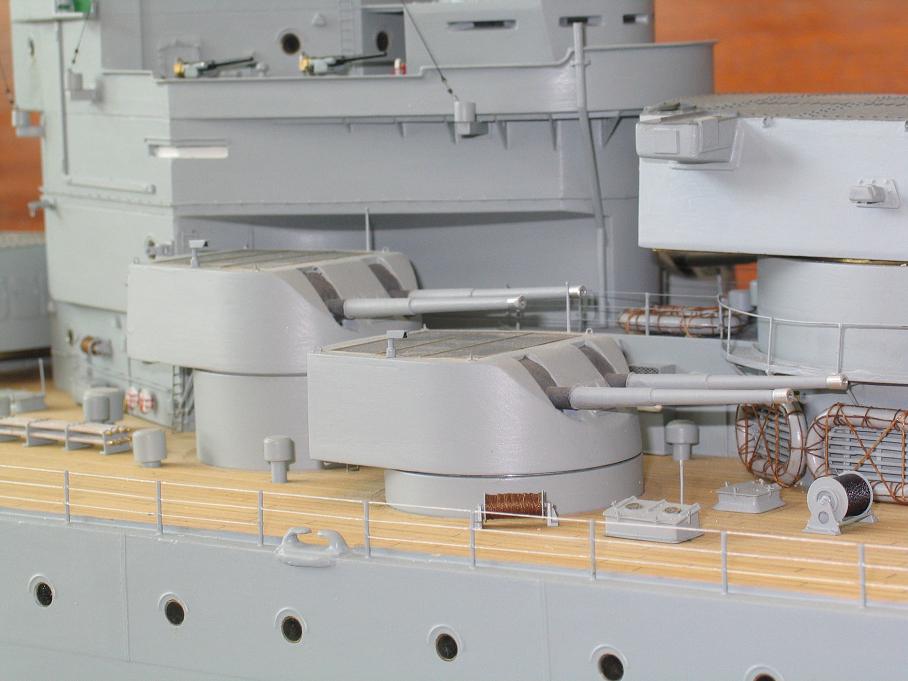
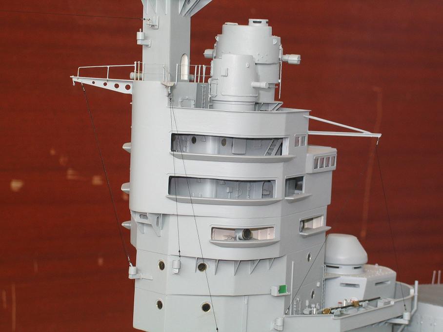
Torpedo defense was largely unchanged compared to preceding designs, the spaces between the longitudinal holding bulkheads were filled with about 2000 tons of water. According to the latest research however a further ‘trick’ was toyed with, similar to what submarines used to blow their ballast tanks in case of emergency. The system involved a valve system that used very high pressure air which could blow out part of this water in case of asymmetrical damage. This way lost buoyancy could be restored in a matter of seconds preventing dangerous heel and other negative effects stemming from that. Unfortunately no further details are known and later British battleship designs had no sign of this et all.

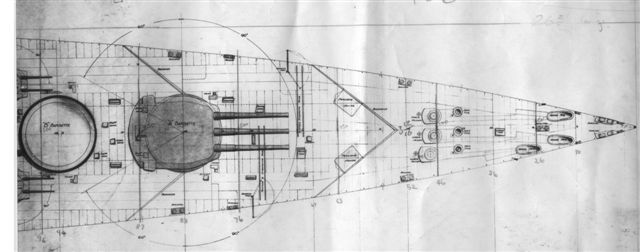
Tenders were sent out on 3rd September to the following ship and armament manufacturers: Beardmore, John Brown, Cammel Laird, Vickers, Fairfield, Armstrong Witworth, Harland and Wolff, Swan Hunter.
The 4 best offers got accepted which were:
- Beardmore, 3.786.332 Ł (machinery sub-contracted out to Vickers)
- John Brown, 3.879.000 Ł
- Fairfield, 3.900.000 Ł
- Swan Hunter, 3.977.175 Ł
The contracts called for a building time of 30-36 month up to the trial runs. Prices did not include the armament, firecontrols and the armor – included were the fully fitted hulls with superstructures and all machinery.
The excluded main components were supplied by the Admiralty who contracted these items to other, different manufacturers, mainly to Vickers and Armstrong. They got the order for the 406mm (16 pcs) and the 152mm (32 pcs) gun houses divided equally with Armstrong supplying three spare turrets. [13]
The 37 (one spare) 16”/45 Mark I gun orders were distributed as:
- Elswick, 13 guns
- Vickers, 15 guns
- Beardmore, 9 guns
The armor plates (except for the turret armor, which were supplied by the turret’s manufacturer) were also distributed between the big players in a way that all four contractor supplied components for all four ships (this way they made sure that building progress won’t suffer too much due to contract breach on any supplier’s behalf).
For example barbettes ‘A’ for all units would have been supplied by Vickers, while ‘X’ would have come from Cammel-Laird; supporting structures for turret ‘B’ coming together by John Brown and Armstrong. The rest of the items were shuffled even more.
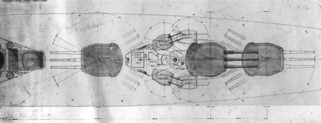

In the end no keels were laid and all the orders got cancelled in February 1922, parallel with disarmament talks in Washington, though more than half-a-million pound sterling was spent on the program and even some penalties were due as the builders were all private companies.
Fortunately not everything was money thrown out of the window as the first two sets of turrets could be reused for the later RODNEY and NELSON, true that even these needed many modifications (mainly lightening) to fit those vessels.
Second tier naval literature often calls these four vessels to be built according to the finalized G3 plans as the INVINCIBLE (II) class. Usually even the individual unit names are described, all starting with relevant “IN-” parts, but official sources give no mention of these so these can be considered conjectural.
Further battleship plans: N3, O3, second half – 1921
As the battleships were postponed to the 1922-23 program their detail design was put on the backburner. The ‘M3’ downselected in Nov 1920 was used as the basis for further development but actual work proceeded only from late summer 1921. All the changes incorporated on the G3 final design were taken over and implemented, including the redistribution of the armor (split thicknesses for BBs introduced which was an important difference compared to ‘M3’) and new secondary battery layout. The reversed machinery with turbines forward remained though as well as the main battery caliber of 457mm.
At the request of the Third Sea Lord the torpedo defense system was upgraded to resist 445kg charges from the former 340kg ones. In order to accomplish this the whole system had to have greater depth to absorb the increased energy so the distance between outer shell and holding bulkhead needed to increase. The obstacle here was the same as for ‘G3’s machinery, the ship had to fit through the locks of Panama-canal, therefore total beam was maximized. There remained no other option but to increase length by 15m and the internal volume gained with this was used up by elongated but narrower machinery and magazine spaces. This of course needed longer armored surfaces as well, driving displacement up by 2500tons in total. As a small compensation ammunition allotment decreased from 100 to 90 rpg. In the end the battleship variant was only 11m shorter compared to the battlecruiser ‘G3’.
Armor stemmed from ‘G3’ with some changes but most thicknesses were inherited from ‘M3’, so this was an amalgamation of the two previous designs. The split thickness only remained on the belt, with 381mm over the magazines forward slimming to 343 over machinery and at the back increasing again to 381mm over half of the aft boiler room and after secondary turret magazines. This increase in the main belt aft was unique to this variant only. The deck protection remained a constant 203mm flat over the whole vital part – with the very slight outward slope from the centerline. Torpedo rooms were also covered by 203mm lower deck and steering gear and leads were protected by a turtle back shape deck aft (152mm thick). Vertical 356mm front and aft transverse bulkheads closed of the citadel.
Main turrets got thinned (compared to ‘M3’) at their backs with 356-245-229 front-to-aft and secondary turrets and their trunks got a uniform 25mm protection and these were moved under the protection of the main belt for the aft two pairs of turrets.
Speed remained 23-23.5 knots with the two shafts and associated larger diameter propellers
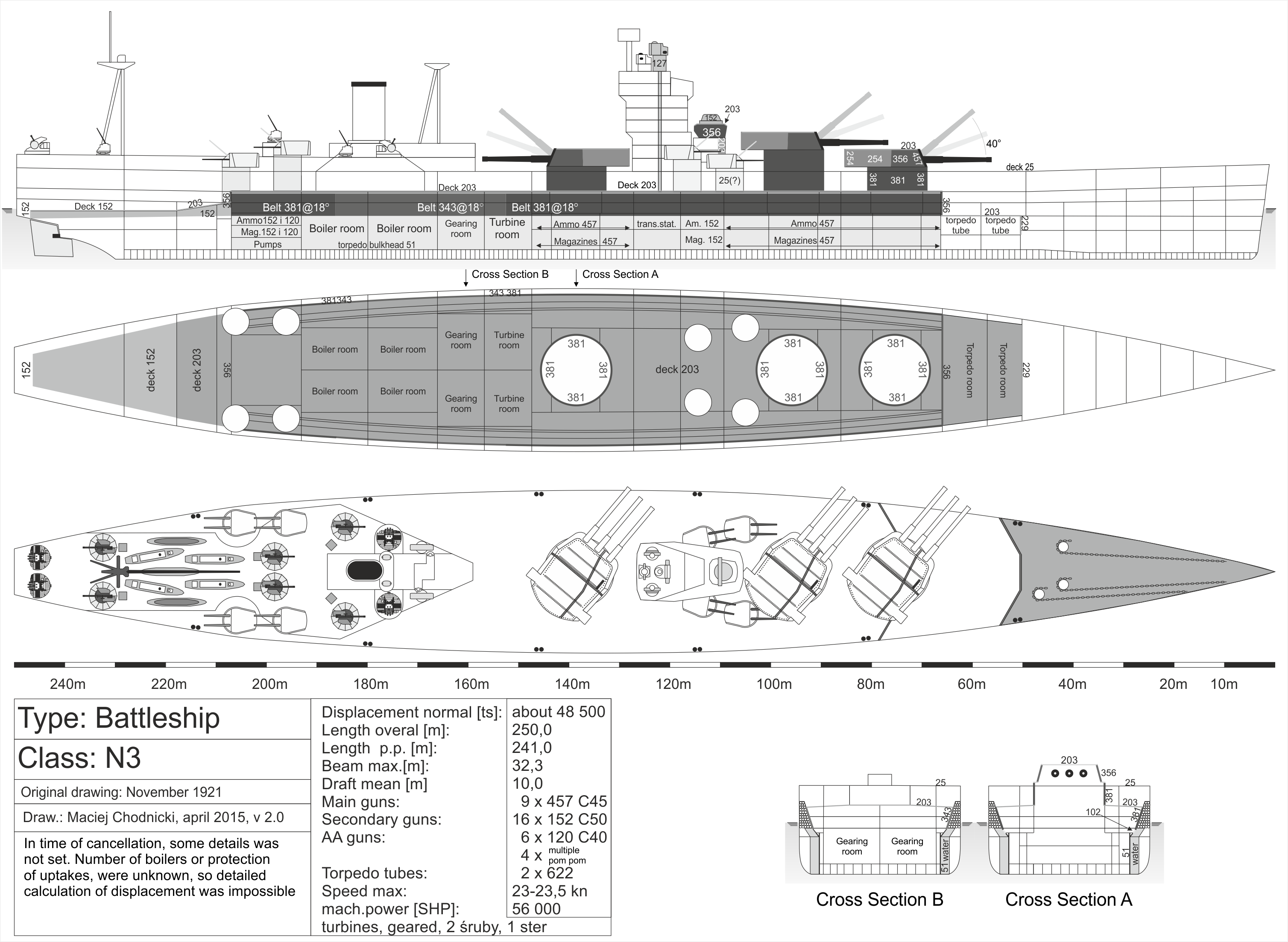
This detailed plan was submitted as ‘N3’ for the Admirals Staff on 6 July 1921. Interestingly the caliber of the main battery was treated in as top secret. Due to this and party because of DNC’s comment toward Attwood in August 1921 (ie that the 457mm gun caliber will be discarded as it was too large and had severe blast effects) a redesigned ‘N3’ came to be which just came to light recently. Also DNC suspected that thanks to the US Navy’s new 406mm ships [14] the Admirals Staff is going to ask for a design with twelve 406mm guns instead of the current nine 457mm gun main battery. This way at least the Royal Navy won’t fuel the caliber race. Furthermore with the ‘G3’s set at 406mm guns it would be logistically advantageous to have the same caliber for both battleships and battlecruisers.
From this train of thought there was no new detailed design, the base ‘N3’ got modified with an additional 15m waterline length and two 16″/45 Mark I three gun turrets put in place both in front and aft of the tower structure, somewhat mirroring the ‘M2’ concept in turret layout. Propulsion was increased to 60.000 SHP to maintain 23 knots and displacement rose to 50.700ts from the base variants 48.000 tons. It was not detailed any further but it is very likely the armor would have been reduced to accommodate a 4th (although smaller) turret and barbette.
The latest research revealed that in fact a further ‘O3’ design was prepared. This was not submitted to the Admirals Staff as it was ready only in Dec 1921 when it was absolutely sure that battleships of the future will be limited to 35.000 tons and 406mm guns by the Washington Treaty. This version was more of a ‘hedge’ bet in case the treaty fails somehow. As we know now it did not and the ‘O3’ marking got reused later for the NELSON class design effort.
This newly discovered design is very sketchy. It is an enlarged ‘N3’ which got the same dimensions as the battlecruiser ‘G3’ in order to maximize the dimensions offered by docking limitations. Based on the surviving information this would have been a 261m long, 51.000 tons ship with 60.000 SHP machinery supported by two funnels, capable of 23.5 knots. Armament mirrored the ‘N3’ with armor somewhat reduced due to greater length, with main armored decks cut back to 178mm over magazines and 127mm over machinery. It is speculated that the two funnels and the longer hull is an indication of either an alternating (ER-BR-ER-BR) machinery layout or a complete redesign for turbo-electric propulsion.
However even the base ‘N3’ variant was not completely finished, for example the exact amount of boilers and the funnel uptake protection details were not set.
In the shadow of Washington: battlecruisers F2, F3
As discussed in Part I., the Five Power treaty also called Washington Naval Conference convened in November 1921. One of the first suggestions from the United States delegation was to limit the displacement of battleships in the future – after much negotiation this was set at 35.000 tons. At this point the limit on gun caliber was still an idea only. Admiral Beatty, who led the British delegation wanted to know what is possible on this displacement so he asked the DNC in secret to develop some sketches fitting into this new standard. Thanks to the battlecruiser orientation of the Admirals Staff the ‘G3’ design got reformatted to a much smaller footprint.
With the introduction of this artificial limit it got more obvious by the day that future ships will all be about balancing between firepower-protection-speed if anything else.
On 30 November the DNC introduced two battlecruiser sketches, ‘F2’ and ‘F3’. The former was the one also suggested by the Third Sea Lord which solved the weight reduction by cutting back the main battery. On this plan there were only six 381mm guns laid out in three twin turrets. In order to keep ‘G3’s armor all the turrets were grouped in front of the tower structure on the foredeck with only the after-most ‘C’ turret in elevated position.
The ‘F3’ on the other hand retained 9 guns in three triples, while the caliber was also 381mm a price was paid in machinery space, where power went from ‘F2’s 112.000 SHP to only 90k here with speed equally falling from 30 knots to 29. Both versions kept the 18°sloped inner belt that had a thickness of 343mm over magazines and 305mm over machinery with 178mm and 90mm armored decks covering them in the same order. TDS was kept at 340 kg resistance however the depth of the double bottom fell somewhat. Secondary armament caliber remained, ‘F2’ had to make with two pairs of twin turrets and singles each while ‘F3’ was left only with two pairs of twins. The two 622mm underwater torpedo tubes were inherited from the ‘G3’. ‘F2’ fitted easily into the 35.000 limit while the bigger brother was already at that number with detail design probably pushing it further up.
However this series remained a dead end as further talks introduced the ‘battleship holiday’ and so the battleship variants did not even make it off the drawing boards and the next battleship design, the new ‘O3’ appeared in the NELSON class portfolio.
Conclusion
Based on the above design history we can safely say that these units would have been one of the most potent surface vessels afloat at that time and even if they were not as revolutionary as HMS DREADNOUGHT they definitely meant an entirely new generation.
The ‘G3’ in it’s final form pretty much neared the ideal balance between battleship and battlecruiser while the ‘N3’ would have been the most powerful and best protected battleship afloat bar none up until at least the late 1920s.
Naval literature offers a mixed bag of opinion about these designs. Some praise them to the level that they compare even with the 20 years younger US IOWA and Japanese YAMATO class ships while some say these were faulty concepts deemed to failure with their strange armament and machinery arrangements and extremely high pricetags.I think it still tells a lot about the military value of these units that even in the financially ruined position of Great Britain after the Great War 4 hulls still got ordered. On the other hand without the Washington treaty the numerical superiority in modern, powerful ships would have inevitably shifted to the other side of the pond with at least 16 up-to-date fleet units possessed by the USN by the time these ships would be built and to this came the 6-7 fast capital ships of the Imperial Japanese Navy.
Against all these the RN could only line up HOOD and four of each G3 and N3. In light of this I think the Brits made quite a good business in Washington, especially that in the end a much shrinked ‘G3’, the NELSON class did get built and they had to face much less scary adversaries. So we can finally conclude that like the LEXINGTON design for the USN this whole story was far from being a waste of time and design effort by the three main characters behind them, and d’Eyncourt, Goodall and Attwood really created something unique and long lasting in the process.
Notes:
[1] QUEEN ELIZABETH and R class battleships plus battlecruisers HOOD, RENOWN, REPULSE’s main battery
[2] the latter with fairly good results – they hold the record for highest range where a British naval gun opened aimed fire
[3] In reality there was an 508mm weapon as well in early development phase in the USA
[4] transom stern: instead of the finely curved hull lines joining together aft the hull ended suddenly with a transverse flat surface, just like the tip of the stern was cut off
[5] earlier, during the QUEEN ELIZABETH class’ further development a similar arrangement was used for preliminary designs ’U4’ and ’U5’
[6] a current day NIMITZ class carrier is approx. 317 m long and 41 m wide on the waterline – so these were quite ambitious numbers for that time
[7] the 293 m distance was between perpendiculars on the outer blocks of the floating dock, meaning that while respecting the 65.000 tons weight limit an even longer ship could fit into the dock
[8] During the dreadnought age several classes had turrets amidships but in each and every case there were additional turrets located on the stern, facing aft without having to worry about any obstruction. So here they clearly sacrificed field of fire directly aft in order to gain better protection. Somewhat humorously we could note that the RN was not afraid that their ships would find themselves in a stern chase as the prey or as one of the officers of HMS RENOWN remarked when her ship was compared to HOOD: “Who needs two turrets aft!?” Jokes aside the past war’s experience and naval maneuvers showed clearly that actual occasions where the main guns fired directly aft were very rare if not non-existent. Therefore the real loss in fighting value resulting from this arrangement was negligible or marginal at best.
[9] DNC remarked that in case the 16.5″/45 does not live up to the expectations they can replace each three gun turret with twin 18″/45 Mark I units
[10] The decks had an actual slope of 2.5°outward from the centerline
[11] it is quite probable that against plunging fire coming from directly forward or aft the shallower 18° slope was actually better as it reduced the chance of such hits landing below the armor belt itself
[12] the HOOD cost 5.8M Ł, a 20 years later the ships of the KING GEORGE V class ran a bill of an avarage of 7.3M Ł calculated at 1940 rates
[13] my main source – N J M Campbell’s „Washington’s Cherrytrees Part 3 – Warship Volume 1” (Conway, 1977)- lists Vickers and Elswick as the winning bidders for the armament: the former taking orders for 6 three gun 406mm turrets and all 32 of the secondary battery gunhouses while the latter taking the rest of the 406mm mounts plus four spares (instead of three)
In contrast Ian Johnston & Ian Buxton’s The Battleship Builders (Seaforth, 2013) references Armstrong and Vickers just as it is described in the text: this one seems more logical as the turrets were designed by Armstrong after all…
[14] They knew this precisely thanks to Goodall’s american exchange trip
Surces (regarding all three parts of the series, in order of importance):
Norman Friedman: The British Battleship: 1906-1946 (Seaforth, 2016)
N.J.M. Campbell: Washington’s Cherrytrees: The Evolution of the British 1921-22 Capital Ships (Warship Volume 1, Conway, 1977)
Maurice Northcott: HMS HOOD (Ensign series – Bivouac Books Ltd, 1975)
Ian Buxton&Ian Johnston: The Battleship builders (Seaforth, 2013)
Norman Friedman/N.J.M. Campbell: Naval Weapons of World War One (Seaforth , 2011)
John Roberts: British Battlecruisers 1905-1920 (Seaforth, 2016)
Norman Friedman: Fighting the Great War at Sea (Seaforth, 1914)
Alen Raven&John Roberts: Die britische Schlachtschiffe des Zweiten Weltkriegs (Bernard&Graefe, 2002)
R.A. Burt: British Battleships 1919-1945 (Seaforth, 2013)
In addition to this I am indepted to the following friends of mine who offered invaluable help and support with comments, sources and drawings:
for David Murfin – who brought design ‘Y’ of Part 1 to my attention and who has extremely deep knowledge of this whole topic that he kindly shared with me on many occasions
for Maciej Chodnicki- for offering Part 3’s nicely detailed and very precise drawings and for sharing his similar Polish writing’s English translation
for Zoltán Takács – who again did an excellent job transferring a rough hand drawn sketch into a nice coloured rendition of design ‘Y’
and last but not least to Norman Friedman who despite his busy schedule answered quite a lot of my questions
Dec. 2017


Dear Sir,
I would like to know how to contact Norman Friedman.
I have some of my own questions that I would like to get answers to.
Kindly reply,
Thank you,
Nunghead
LikeLike
Hi,
unfortunately I can not directly share his contact but you can try to reach him trhough Warship International infoser section.
Akos
LikeLike