Yamato is probably one of the most well known ships of the Second World War however most articles focus on the ship as completed and it’s somewhat boring but in the end still dramatic career. I would like to focus on the development side (A-140 onwards) and how the final design (A-140F6) was reached with a brief look at subsequent planning for the improved-Yamato designs (A-150).
Overview:
The design for the class of battleships known today as the most powerful gun-armed and armored warships ever built, the Yamato class can be traced back to the very early 1930’s, namely to the First London Treaty. This conference was conveyed in order to extend the sanctions on naval buildup imposed by the 1922 Washington Treaty – and in general it can be said that it did not favor the Japanese Navy any more than the previous restrictions. What’s more it restricted the total number of cruiser category ships that each navy could field – formerly this limitation applied only to capital ships (ie. battleships, battlecruisers and carriers).
Around this time the Japanese Navy’s design bureau had two iconic designers, Admiral Yuzuru Hiraga and Adm. Kikuo Fujimoto.
The latter, Fujimoto was head of the design department and as such responsible for most novel ship designs made (Fubuki class, Mogami class for example) while Hiraga was his predecessor (replaced in 1925), now working for the Navy’s research department. Why this is absolutely relevant is that their influence on the A-140 design process was huge and can be clearly seen as they shaped it from one extreme to the other. The two men were classmates at the University of Tokyo yet they were absolutely opposite of each other. Fujimoto had extraordinarily good strategical view on things and he was a firm believer in modern shipbuilding practices, like electric welding, diesel/combustion engines and use of indirect protection with many layers of armor instead of one thick layer and minute subdivision of the hull to prevent progressive flooding. He also had a strategic concept and designed his ships to fit that (more on this later). What really counted though is that he was willing to adhere to the wishes of the Naval General Staff (NGS) and was keen to satisfy their needs of putting more and more armament and machinery in ever so smaller and lighter hulls – no matter how much this reduced safety margins.
Hiraga on the other hand was a well experienced and excellent designer (Nagato, Tosa, Amagi classes were all his work with Yubari his trademark). Hiraga was more of a ‘believer of his own theories only’ type of designer and he was not really wishing to subdue himself to the NGS’ ‘we want it all’ approach – that is one cited reason for his replacement. He was committed to massive direct protection with huge amount of armor and long and unprotected hulls with insufficient subdivision.
On the downside Fujimoto was a heavy drinker (probably has to do with his relatively early death) which did not help his reputation in the Tomozuru accident case; while Hiraga was fairly close minded on strategic views and was someone who would be characterized as a non-creative thinker in today’s world. Although the Yubari showed some novel shipbuilding features (structurally integrated armor for example) it still lacked sea-keeping and tactically it did not really fit into the navy, as it was slower than the old 5.500 ton light cruisers it intended to replace and also had very limited range compared to the 10.000+ tons heavy cruisers the navy sought after really.
So the somewhat conflicting and rivaling yet ambitious planning of these two designers shaped the Imperial Japanese Navy’s ultimate battleship class from the get-go.
Japanese warship design pre-Yamato generation:
Fortunately for us, the late Adm. Hiraga passed most of his studies, works, notebooks, memos and plans down to this generation. From his online archives at the University of Tokyo we know that he was very keen on keeping up with what’s going on at other navies, especially at his mentor’s (the Royal Navy) doorstep. This also highlights the extremely close relation to the British to the point that most design calculation sheets and notes were done in English with very minimal Japanese on them! From there and from other British sources (like Brass Foundry Archives) we also know that basically all major Japanese warships up to the Nagato class bore some influence of British design firms, especially Vickers and Armstrong and their designers had major impact on the Imperial Japanese Navy. Starting from the Kongo class where the lead unit was even built at Vickers the influence was less and less on progression of each class. These British companies offered many designs up until at least 1920 for the Japanese and they show strong resemblance to the actually built Japanese ships, so at least part of the design work was done in the UK. From the Nagato class/A-102-110 onwards (up to and including subsequent classes A112-128 and B64A-G that got cancelled by the Washington Treaty) Hiraga himself took over the design work more and more, and I think these showed a lot of uniquely Japanese solutions and detail parts, but in overall concept still reflected RN thinking. After the Washington Treaty of 1922 the British-Japanese alliance got dissolved officially, but what is tantalizing is that Hiraga had fairly accurate drawings and technical details of the latest and greatest what the RN had on the drawing boards, including all the preliminary designs for G3 and N3, plus even the actually built Rodney and Nelson (Design O3) whose exact details were not clear even for the US at the time!! So while the A-140 design effort was genuinely a Japanese product it still relied heavily on some British concepts defined by their aforementioned ship classes (turret arrangement, internal belt armor, all-or-nothing protection etc.).
Despite all this it is clear from the amount of design work and effort put into the A-140 series that the Japanese tried to build the best and most powerful battleship in the world on their own and as such it makes it an even more impressive first attempt.
Prelude:
In 1928-29 as the Washington Treaty was set to expire soon it was just natural that the head of the design department and the highly regarded technical adviser both produced sketches for what they considered to be the battleship of the future. For a high level Technical conference held in 1929 they laid out several designs which were using the same basic principles yet varied in armament and arrangement to satisfy a range of options. All of these reflecting their respective school of thoughts while keeping the maximum 35.000 tons displacement limit (some were smaller) set by WNT in the planned Kongo/Fuso class replacement program. In the end none of it came through due to the London Treaty which further extended the ‘battleship holiday’ with 5 more years in 1930 but it was a good indicator of what was to come.
Hiraga’s designs

had an extremely concentrated citadel with very heavy protection in it. The armor cross sections are clearly showing similarities to the one later adopted for the actual Yamatos with thicknesses already being very impressive (some had 15″/380mm inclined belts). However the designs featured typically Hiraga-esque very long and unprotected bow and stern parts and also showed very old fashioned casemate-tpye secondaries mixed with turrets.
30.000t version with 3 triple 35,6cm guns:

35.000t version with 2 quad and 1 twin 41cm turrets:

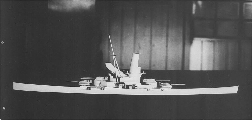
The most famous is of course Design “X” thanks to Herr Breyer’s well known almanach book on battleships. This might have been done somewhat later (July 1929) as it shows 10 guns in two triple and two twin turrets. Recent information from Hiraga Archives also show that both the main and secondary battery used new gun designs: a potential 41cm/50 for main and a dual purpose (!) turreted 14cm/55 for secondary. Even the casemate locations had the elevation for AA mode (75°), but eventually these weapons were substituted for the classic 15cm/45.

Above: Design “X” layout (note the secondary’s elevation) Below: Armor cross section

Quite probably this was the preferred design by the Naval General Staff as even a model was made of this version:
What is much less well know is that in September 1929 yet another design was sketched up by Hiraga (he really wanted to be part of the design team for the next big thing), this time he tried for an unrestricted design, with nine theoretical 45cm guns comprising the main armament. He chose the Nelson-stlye layout, all turreted secondary armament (3X3-20cm) moved aft of the superstructure and separate high-angle guns (6X2-12.7cm) located very high up on the main control tower. Protection was on a similar scale, main armor on magazines, turrets and CT was to protect against 45cm shells between 20-30kms and 25-30kms on machinery parts. Propulsion consisted of a mixed diesel-turbine setup, approx. calculated at 200.000 SHP to make 32 knots. Waterline length almost reached 290m with a 37m beam and 10.2m draught. Turrets 2 and 3 held catapults on top and we estimate that these would have been served by the same stool like aircraft elevator that was used on battleship Fuso just a few years later. At present (summer 2018) this sketch is thought to be the earliest directly related design to the future Yamato-class as it had many of the essential elements the somewhat later A-140 series are famous for, but still retained quite a lot of external similarity to the above listed 1928-1929 designs.
62.000 tons preliminary: the earliest ancestor of Yamato

Fujimoto’s approach
was somewhat different in that not only did he conceptualize a single ship design but an entire strategy. In fact the most authoritative source for his design(s) is Hiraga’s archive, with the below drawing. Actual details are very vague on this one.
Fujimoto’s 35.000 tons compliant design with nine 41cm guns

What is apparent though that he already had his trademark features: the mast-stack combination, the spoon like blunt bow with a fairly vertical fair-water. All this combined with the undulating sheer line both forward and aft, cutting down hull height and saving weight while offering good placement for the secondaries. These secondaries do appear to be the same HA mountings that are evident on the Hiraga counterparts as well. What is not clear though is the armoring (or the lack of it) on these outside-the-citadel 14cm twin turrets.
14cm/55 twin dual-purpose turret

Secondary sources also show a 4 turret variant of Fujimoto’s ship but these sketches appear to be somewhat generic and have separate funnels and aft superstructures with main mast on them, while the secondary turrets are laid out in a different pattern as well. All in all they appear to be based on some verbal description and no primary source backing was found as of yet.
What Fujimoto had in mind however was a masterfully worked out, however extremely ambitious building plan from 1936 running up til 1950. Unhappy with the outcome of the Washington and London treaties and being aware of the numerical and industrial advantage that the United States enjoyed over Japan it was an obvious choice to focus on quality instead of quantity – that is, going big…very big! In a typical Japanese fashion it was based on the expected ‘movements’ or ‘behavior’ of the likely enemy, the United States Navy. Since it was well know that the US Navy had an artificial limit on it’s battleships size, namely the locks of the Panama Canal – it imposed a 33m beam limit and a length limit of approx. 300m – so the IJN made 5 design studies to estimate maximum possible USN battleship size. These were pretty accurate, to the point that one design was a few percent off only compared to the historical Iowa class. Based on these designs the Japanese engineers had a good idea how large to go to beat the US ships on a one-on-one basis. Gun caliber was estimated at 16″ for all the pseudo-US proposals so the Japanese automatically opted for 18″ weapons. And this was not all! What is not well known is that Fujimoto expected the US to raise their BB’s gun caliber to 18″ as well by 1941 as a response to the Japanese ships so he aimed from the get go to design the triple 18″ barbettes to a diameter that can easily handle a twin 20″ turret – and rearm the BBs during 1941-46 with the bigger guns! In addition 4 enlarged, “Super Yamato” class ships with 8 X 20″ guns were planned to be built during the same period, giving 11 BBs with 20″ guns for Japan by 1951, and giving the Japanese a supremacy in gun caliber for 10 years. This is evidenced by the fact that the Mogami and Tone classes designed by Fujimoto as well were built with the same concept, built or designed with 6″ guns and rearmed to 8″ on completion or before the war. Also there is evidence of a 20″ Japanese gun, though not much of it is known.
Actual design work was put on hold from 1929 to 1932 due to the London Naval Treaty of 1930 and really picked up in earnest in 1934 again. The reason this time was the League of Nations sanctions on Japan for the “Manchurian Affair” and their withdrawal from there coupled with Japan renouncing their London Naval Treaty obligations as well.
This opened up the way immediately for the so-called Super Battleship Strategy laid out above. While no designs were made research work was going on in the background during the 1929-1934 period as well with primary focus on:
-a.\ main battery arrangement
-b.\ diesel propulsion engines
-c.\ bow forms/hydrodynamic development areas
For point a.\ the semi-capital ships of the treaty period, the Type A or heavy cruisers offered a good testing ground. From the Aoba class (which was Fujimoto’s improved version of Hiraga’s somewhat botched Furutakas) they used superfiring gun turrets mounted in armored barbettes, similar to battleships. The Myoko classs, originally designed by Hiraga but later taken over by Fujimoto for improvements, raised the bar and added two more heavy turrets to the main armament, laid out in a Nelson style layout on the foredeck (with turret 3 facing aft) and a superfiring pair at the back. To be able to support 5 turrets the ship had to be fairly long but in order to maintain high speed it had to accommodate a lot of machinery in a narrow hull pushing out the two groups of turrets to the ends. This created massive bending forces and stresses in the relatively lightly built hull which were exaggerated by the distance between the turrets leading to massive dispersion issues when the entire main battery fired together.
The next class of cruisers, the Takao group tried to improve on this. Responsible for this was Fujimoto’s eager assistant and protege, Iwakichi Ezaki, who with the lead of his mentor redesigned only the middle part of the previous class and shortened it by moving the superstructure almost entirely over the forward group of boilers and their smoke pipes, creating the castle like appearance of the Takao‘s forward superstructure. Unfortunately this did not solve the problem entirely and also had a massive negative effect on stability with raising the center of gravity. The Mogamis came next where the arrangement of the forward turrets got changed with two forward facing turrets in line sitting on the bow at main deck level and a third, superfiring turret added in behind them. An additional, continuous upper deck was also added between the forward and aft superfiring barbettes, with the intention to stiffen the hull in this part. To combat the stability issues the bridge structure was much simplified into a tower like structure and it’s height was somewhat reduced as well. Unfortunately this layout was not entirely successful at first either as it transferred the stresses from the hull to the raised barbettes and many times jammed their turrets in train (this was solved later). In the final pair of heavy cruisers, the two Tones Ezaki dispensed with the 5th turret and used the Takao layout with an additional aft facing turret at main deck level, forward of the superstructure. This concentrated the four turrets in one group and made for an excellent gun platform, while also cleared the aft deck from blast issues.
Point b.\ was addressed with building some diesel powered auxiliary ships, most notable being the submarine tender Taigei in 1933 which also was a test bed for electric welding. As it later turned out both fields of interest were falling short of expectations, with the diesels giving only around half the hoped for power output (14.000 instead of 30.000 SHP) and a lot of stress induced cracks appearing on the hull stemming from poor welding techniques. Of course both factors were later improved upon, especially the arc welding came a long way but the last minute reversion to fully steam propulsion was in no small part to issues with Taigei’s diesels.
Finally c.\ was aimed at getting the best performing hull-form from a hydrodynamic point of view. It was pretty obvious early on that a 60+ thousand ton battleship has to have wide beam and to maintain high speed with any reasonable amount of horsepower all they could get out of hull design was needed. To help this a huge amount of water-tank tow tests and calculations were done plus some real life tests were run on the then demilitarized battlecruiser Hiei before her upgrade and rearmament to a battleship.
In fact Hiei was rebuilt with parts intended for the new battleships so she was a testbed for the tower structure layout and fire control equipment that was later used on the Yamatos.

Early ship and gun designs
Fujimoto appears to be a good politician/tactician as well as he made sure he has a strong backing in the Admiralty staff so somehow he arranged for Ezaki (who got promoted to Vice Adm.) to be part of that body while keeping his role as constructor! It is assumed that this was to push his Super Battleship Strategy and all-forward battery with diesel propulsion ideas through and also to keep Hiraga’s influence minimal or at least to keep him ill-informed about what is really going on. Hiraga on the other hand wanted a slice of the cake badly and kept submitting his input and personal designs as chief of the research dept. – he had all rights to do so thanks to his position. Fujimoto, in order to prevent these ideas gaining traction with the NGS (as it happened in 1929) ordered Ezaki to comply and cooperate with the Admiralty staff as much as possible.
This bitter rivalry probably created the situation that the wishes of the operators, that is the Admiralty, had too much influence on ship design and forced Fujimoto and Ezaki to draw up ships that were borderline unrealistic and unsafe from a ship construction point of view and as such did no good for the final product.
Design work for 46cm and 51cm guns and mountings with common shell and powder transportation systems were undertaken from April 1934 already. At least four 46cm variants were investigated, two 45 and two 50 caliber length versions in both twin, triple and quad turrets. For the use of these mountings and in accordance with Fujimoto’s ideas Ezaki sketched up two entirely diesel powered designs in July 1934, both using 46cm triple turrets. Hiraga’s idea for using both twin and triple turrets at the same time was rejected this time.
The bigger one (67.000 tons standard, 301m/990ft length) aimed for 31-33knots speed with a 6 (!) shaft all-diesel propulsion and it’s immunity zone against 46cm shells was the requested 20-35km range. Main armament was all forward with Mogami style arrangement. Note the Hiei type tower structure.

A somewhat smaller version (50.000 tons standard, 289,5m/950 feet) had it’s speed reduced to 28 knots and had only 4 shafts and 0,3m/1 feet less beam with ‘IZ’ coming in at 20-30km only. This one used a Nelson style layout for the main battery, again all forward to reduce blast issues.

From the get-go it was forbidden to write down the 46cm caliber (always referred to as 41cm special type) and it was kept entirely secret during the whole life of the design period and even through the career of the ships (US Navy getting confirmation only in 1946!). The 46cm weapons were extremely powerful at that time – especially that a 50 caliber length version was looked at – so far only the RN had two examples of similar caliber guns actually put on ships and even those were 35 cal. length only. The power of the guns also meant that they generated extreme blast during firing, pretty much enough to destroy anything, even smaller gun turrets in their radius. And even worse was expected from the planned 51cm (20″) guns that are ought to come on board. So it made a lot of sense to group the heavy guns as closely as possible, preferably into a Nelson class like arrangement where all the heavy gun turrets were on the foredeck, leaving the aft free for aircraft, boats and smaller caliber guns.
Unfortunately for Fujimoto the torpedo boat Tomozuru capsized in a heavy storm due to insufficient stability margins in March 1934. That ship was his design, essentially being a halved version of the Fubuki class destroyers. The incident sent shockwaves through the navy and a lot of investigations followed, informally restricting Fujimoto’s authority as head of design (that is why Ezaki drew the first versions I think). Fujimoto was later relieved of his post but after the investigations were completed -which admitted that the Admiralty Staff was equally responsible thanks to excessive demands on weaponry for a given hull size – he was called back to his office in January 1935. As fate would have it he died on the next day -maybe a result of his drinking habits or some internal revenge…
The story takes a U turn here as Rear Admiral Keiji Fukuda took over as the head of the design department and he was a trustee of Hiraga…
It belongs to here that in October 1935 bad weather stroke again when the Fourth Fleet got caught in a typhoon and several ships, many of those designed by Fujimoto were damaged, with cracks appearing on their hulls, clearly indicating that something was not right with these ships. Consequently Ezaki was dismissed from the Design Bureau and only his connection with the Admiralty Staff (and their desire to further press their ideas to the design team) reversed the decision. Nevertheless he was never allowed to do ship design again and quite ironically worked on hull strength calculations thereafter.
Hiraga was called up from reserve to act as temporary adviser and as such he got almost full control thanks to his very good connections with the Navy Minister and the Chief of the Admiralty Staff. The mistrust due to the Fourth Fleet incident between the Admirals and the design department also helped him a lot to put his ideas to fruition.
One of the August 1934 preliminary designs, presumably already done by Fukuda: 55ktons standard with a 100.000 SHP diesel plant for 26 knots with 9-46cm, 8-15cm and 8-12.7cm guns; armor was again versus 46cm between 20-30km

Official Designs
Finally in October 1934 preparations for an official battleship design were put in high gear (in line with Japan’s renouncement of the naval treaty obligations) with the NGS giving direct orders for designing a new battleship to comply with the following requirements:
Main battery: at least eight 46cm guns
Secondary battery: twelve 15cm or eight 20cm guns
Speed: 30 knots
Range: 8000nm at 18 knots
Armor: full defense against 46cm AP shells between 20 – 35km
Torpedo defense: to withstand at least 300kg TNT charges
A-140 – March 1935
Fukuda prepared his first official plan accordingly, with all the features Hiraga wished included and inherited from his 1929 maximum battleship design: armament and superstructure concentrated in the middle part with the shortest possible armored parts. The belt was partly internally mounted and inclined with great thickness. One cannot help but notice that Hiraga applied everything that he learnt from the Royal Navy’s G3 class design effort and the actual design almost mirrored those ships with the main armament layout of the later materialized small-sister of the G3, the HMS Nelson. Of course dimensions were a lot bigger but otherwise the similarity is remarkable.
This was definitely a base line design to show what is technically possible rather than being a practical ship and most Japanese sources do not even mention this as a separate design. The reason for this was it’s excessive size, it’s length (965’/294m) and humongous beam (135’/41m) was unheard of and way too big to be accommodated into any of the existing naval facilities. The hull depth was quite good though and draft was only a moderate 34’/10,4m so at least she could have navigated some of the naval ports. Displacement was also a relatively moderate 69.500 tons standard and the 200.000 SHP steam turbine only powerplant allowed for a 31 knots top speed. Range was 8.000 miles at 18 knots.
The all forward main battery allowed for the best protection to be provided for the magazines as they occupied the widest part of the ship in the middle and what’s more they allowed for a blast-free after deck. Although there is no surviving drawing for this baseline variant it is quite probably going to receive the same middle deck extension to the forward barbette as the subsequent designs. This was needed to have proper strength despite the aft-wards descending sheer line. Also it is quite probable that the 4 triple 15,5cm turrets would have been clustered on the aft deck, just behind the superstructure.
Although there is indication that this set of specifications were discussed on the 10th March 1935 quite probably there was no drawing made and it really existed only as a verbal starting point for the design effort.
A-140 with nine 46cm/50 caliber guns as the main battery

A-140A, B, C, D, A1, A2, B1, B2 – April 1935
Based on the baseline A-140 version a technical conference was held on the 1st of April 1935 in order to further discuss and develop the plans. Fukuda put in a whole lot of work to prepare for this conference and he prepared 8 versions for the meeting.
1.\ A-140A was basically a mixed turbine/diesel version of the baseline variant

The space and weight saved was used to shorten the ship (277m/908′) and beam was also reduced by almost a meter to 40.4m (132′) but displacement only went down to 68.000 tons standard. This lends credibility to the speculation that the vanilla A-140 was a verbal exercise only since the hull dimension differences alone would have meant a much larger reduction in weight.
The steam plant gave 132.000 SHP with 8 Kanpon type boilers while the diesels put out 68.000 SHP for a total of 200k and speed was estimated at 30 knots. However the range increased to 9200 miles at 18 knots. Armor belt was already a dual inclined affair with the upper part inclined at 25° and reaching below the waterline where it had a knuckle and continued toward the bottom at 17.5° angle. The upper part was 17″ (430mm) thick and it continuously tapered down to 6″ (150mm) at the very bottom. This lower part also acted as the main torpedo bulkhead and the relatively high thickness (usual torpedo bulkheads were 1-2.5″) is probably due to the very thorough diving shell test done on battleship Tosa in the early 1920s. Front and aft main bulkheads were inclined at 17.5° and were a uniform 14″/356mm thick. Armored deck was 9″ to 5″ (229-127mm) depending on the area it covered while the lower decks foreward and aft came in at 3″ (76mm) and reached up to the bow and to the steering gear’s armored box respectively. Gun turrets and conning tower had a maximum thickness of 23″ (584mm).
Main armament was still in 3 triple turrets all forward in Nelson arrangement, with three 46cm/50 guns in each turret (130 rounds per gun ammo).
Secondary armament was again distributed aft in 4 triple 15,5cm/60 gun (150-200 rpg) turrets acting as a defense versus smaller ships supplemented by 8 twin 12,7cm/40 DP guns (200 rpg) laid out in a row on both sides of the superstructure with two raised and two on-deck mounts. This secondary arrangement was somewhat awkward and while it reduced blast interference with the main battery it also severely hampered gun arcs, especially on forward bearings.
An interesting new feature already present here – a further measure to blast protect aircraft and boats – was the cut down aft deck with two catapults and a ramp connecting the flight deck with the main deck and the hangar (later replaced by a small elevator on the final design). The ramp served a small hangar for 6 seaplanes which was located aft of the 15,5cm turrets under the middle deck. Next to the hangar on both sides there were two boat stowage tunnels covered by the side plating with a top-rail mounted running crane servicing the boats. These two items survived to the finally selected design and the Yamatos were built accordingly.
Although around this time the rise of torpedo bomber aircraft and aircraft carriers were well underway in the Imperial Japanese Navy there was only a very limited number of machine guns, with 12 twin 25mm weapons placed on the command tower in all designs up until the F series.
2.\ A-140B was the other major design with all-diesel power

The NGS was still massively interested in all diesel propulsion as it offered comparatively more range with less fuel load and also almost completely eliminated smoke interference while also drastically reduced long and vulnerable funnel uptakes and smoke pipes, a traditional weakness in battleship armor-schemes. There were only two boilers that serviced auxiliary machinery so the diesel motors provided all the 140.000 SHP which allowed the much smaller ship (60.000 tons) to still reach 28 knots with the same 9200 miles range at cruising speeds (18kn).
The massive size reduction of the machinery spaces allowed a waterline length of only 247m while beam and draft remained the same which allowed an identical level of protection to be retained. In fact armor and armament was exactly matching A-140A’s. Only the 12,7cm/40 mounts were distributed differently: with the massive funnel gone there was now free centerline space for one mount in front of and aft of the command tower. The aft superstructure incorporated a mast-stack (mack) combination that also served the auxiliary boilers.
Designs A-140A and B were the main focus of the 1st April meeting as they reflected the ideas of the Admiralty staff and allowed a good comparison between mixed and all diesel propulsion in contrast to the baseline A-140 variant of March.
3.\ A-140C and A-140D were attempts to further cut size

Version C was basically a B with weight saving on the machinery side: with 1/4th of the diesel motors removed (a reduction of 2000 tons for 58.000 t standard). Speed fell to 26 knots with 105.000 SHP. Everything else was as B.

Version D was essentially a B with savings on the armament and armor. Standard disp. was therefore reduced to 55.000 tons. Machinery was unchanged from B and this allowed 29 knots speed.
Main armament though was reduced to nine 41cm/53 guns in the same Nelson stlye layout. Armor was also cut, with the belt being only 15″/380mm thick, decks at 8″-5″ (203-127mm) and the gun turrets and CT coming in at only 18″/457mm. Immunity was probably calculated against the smaller gun here.
4.\ A-140A1, A2 and B1, B2 – Fukuda’s influence

The Admiralty Staff was very keen on using all-forward main battery layouts , probably due to this being the best way for later conversion to 20″ (51cm) guns as those were expected to have even more serious blast issues. On the other hand Hiraga’s relation to Fukuda and in turn his influence meant that he tried to convince the admirals through these plan versions about the merits of the orthodox gun arrangement.
A redistributed three triple turret layout with two forward (superfiring) and one aft scheme was applied to both the mixed and the diesel propulsion variants, these were A1 and B1 respectively. In 1935 this arrangement was pretty novel, no ship actually built up to that point had it and only a handful of designs (mostly US ones and some British) used it, but these were most probably unknown to the Japanese.

The modification meant that the main magazines and the citadel occupied more space (144m vs 136m in A1 and A resp.) and they had to be pushed out to the corners (that is much closer to the outer plating) while also complicating secondary battery layout. With four 15,5cm/60 triple turrets and eight 12,7cm/40 mountings it required considerable ingenuity to place them into positions where they offered good coverage with usable firing arcs while solving ammunition supply and yet keeping them relatively blast free. Arguably this latter was not entirely met as the wing 15,5cm turrets would be right under or very close to the muzzles of the aft 46cm guns when firing forward at extreme angles with low elevations – therefore it’s forward angles were restricted to 60° from the lateral while in the all forward version the third turret could train to 75° forward from the lateral. Still there was a potential gain of 60° arc on the aft bearings with the split layout. What was a notable new feature that survived to the final plans though is the aft secondary turret superfiring over the aft main battery turret.
Dimensions, standard displacement, propulsion and armor was the exact same as their respective all forward variants (A and B).

Fukuda tried for twin or two gun turret versions as well, probably on agitation by Hiraga.

The method was the above one once again, the all forward versions got modified with two pairs of superfiring turrets, one forward, one aft. Dimensions and displacement, armor and propulsion again was kept the same. Obviously four turrets took up more centerline space than three, even with the two gun barbettes being smaller diameter individually so considerable jockeying was needed to squeez in the same secondary battery into these versions. The bigger 15,5cm/60 triple turrets were grouped around the aft pair of main turrets, with two secondary triples in forward facing superfiring arrangement were tucked below main turret number 3’s overhang. This was a less than ideal place with massive interference on forward bearings and also very restricted forward and aft fields of fire. The other two triple 15,5cms in the wing positions were moved aft, next to the gap between main battery barbettes 3 and 4. Again this was a seriously handicapped position and even allowed for the 15,5cm barrels to collide with the 46cm guns of turret 4 if not turned carefully on certain bearings at low elevation. We assume the reason for the wing turrets still being placed there is the lack of below deck space next to the superstructure: the sub structures and magazines would simply not fit there due to the machine rooms occupying that space.

The 12,7cm/40 emplacements were in a somewhat better shape but the one in front of the command tower on A2 had to be moved to the very aft of the superstructure where it was blocked on aft bearings.
The four twin turret layout earned better firing arcs and more redundancy for the main battery but reduced firepower by one gun so it was a questionable trade-off.
All subsequent variants were inspired by this series, so they were essentially a refinement of one of these above ones.
The NGS’ designs: A-140G, G1-A, G0-A and G2-A – May-August 1935
The NGS favored A and B from the first series so it was concluded on the April meeting that in future designs the ratio of steam turbine and diesel power in the propulsion units will be at a ratio of 1:1, effectively furthering design A as the primary choice as they still preferred all forward armament.
What was disliked though is the excessive size, especially beam wise on the first series. A further point for improvement was main battery firing arcs on aft bearings.
To answer these first A-140G was born in May, and it is assumed that this and the entire G series were created by the NGS or was very closely dictated by them.

Clearly they are derived from A-140A with much smaller dimensions, in return giving up speed and endurance plus main battery caliber length got reduced to /45. Length was cut to 273m from 277m while beam was substantially slimmed to a more realistic 37.7m (down from 40.4m). This decreased displacement to 65.800tons standard. Propulsion was 70.000 SHP steam/70.000 SHP diesel for a combined 140k and 28 knots. Range decreased somewhat to 8000nm due to smaller tank capacity. Interestingly draft remained at 10.4 meters which was only 0.1m (1′) more than A-140A.
Secondary battery was similar to ‘A’ as well, the wing turrets were probably moved a bit forwards and the number of twin 12.7″/40 mounts got reduced to six.
In July yet another reduction was suggested, this time the length was further shortened to a mere 245.5m (805′) in what was A-140G1A.

To compensate for this beam was somewhat increased back to 38.9m (127.5′) but still displacement was down to a mere 61.600 tons. In order to lower displacement to this level speed that is propulsion and tank capacity had to give. A 115.000 SHP total plant (split in almost half again between 55k diesel/ 60k turbine) for a lowly 26 knots was combined with a range estimated at only 6.600nm at 16 knots. This became the new standard instead of 18 knots for all subsequent designs, probably to reflect the lowered speed requirements (lower top speeds also meant lower economical cruising speeds) and to somewhat redress the endurance numbers.
Furthermore deck armor got reduced somewhat as well with the outer edge of the Immunity Zone being at only 27km instead of the so far standard 30km.
The exact deck thickness is not know but G1A definitely had a fully flat main armored deck instead of the previous flat middle/downward sloped side strakes combination which had the advantage of offering higher protected volume with less armored belt height. Here either the belt was raised or the deck lowered so that it can be fully flat. The belt was angled at 15° so it is likely that the former has happened but this is speculation only – see more details below.
With an Atago style main battery layout on the foredeck (that is turret 3 was facing aft) field of fire was opened up somewhat (approx. 10-10°on each side). However the short length pushed the machinery really aft creating a relatively cramped ship.
In the July-August timeframe work picked up in earnest and most of the remaining preliminary designs were submitted around this time
A-140G0A was next from the NGS’s series and it essentially restored speed to 28 knots while keeping the Atago arrangement and the better aft firing arcs.

This came at a sever cost as the 268m length even with the same beam and draft meant a displacement of 65.450 tons standard. Of course the larger hull could take on more machinery and fuel tankage so it would have had 70.000 SHP diesel and 75.000 SHP steam turbines and a range of 7.200nm at 16 knots. Essentially this version combined the advantages of the previous two.
During August three more unnamed design submissions were made as well, similar in many respects to the G variants, with 26-27 knots speed. Length varied between 244 and 249m while beam and draft was still the same. All had split propulsion systems, 110.000 SHP for the 26 knotters and 130.000 for the 27 kn one. Armament was again similar to Nelson style however turret No. 1 gave up one gun so these were all 8 gun battery versions. This was probably needed to stretch out the main battery a bit and make the ship less cramped while still retaining enough space for a TDS aside barbette No. 1.
For sake of identification we call these A-140G1-B, C and D. This latter is shown below.

The final say came at the end of August from the NGS with A-140G2-A.

Some artistic license was taken on the drawing to show the final hull form, reflecting an A-140 that was probably closest to what Fujimoto would have settled for. This version was more or less an acceptable compromise between firepower, protection, speed, endurance and main battery firing arcs. (Ironically dimensions, displacement and armament was within a few percent to what was actually built, even if it was a different layout.) It was not excellent in any of these but was good enough everywhere while still retaining an all-forward arrangement that was so beloved by the NGS. Ezaki was finally dismissed soon after, completely ending Fujimoto’s late influence on proceedings.
Armor protection
It is essential in a battleship design to have various armor schemes considered, especially when protection was needed against very powerful weapons. Unfortunately there is no really detailed description about the rest of the A-140 series protection after A-140D other than IZs, but there are some small nuggets of info. Primary sources (Hiraga archive) indicate changes or suggested alternatives in the armor layout from G1A onward in addition to the flat main armored deck. It seems several options were investigated and there were detailed stability calculations done for each. Options mainly concentrated on the belt armor and the armored deck height and of course this was in conjunction with the flat or sloped side decks described above.
We have found details for 4 cases:
– Standard: 20° slope on the armor belt on the whole citadel with 25° forward and aft canted main transverse bulkheads making up the vertical protection. However belt height was not uniform, with a higher part forward (probably for the all-forward variants) and a lower aft. The higher part connected to the main armored deck (AD) with a 10°downward sloping outer strake while aft the lower part had no slope and the AD was completely flat above it. The armor belt was external above the waterline but tapered down right to the double bottom behind a bulge, acting as the main torpedo bulkhead.
– Case (I): sloped strake AD but equal height belt over both machinery and magazines. The belt was at 20°above the waterline part and tapered down still but the torpedo bulkhead part was at a much shallower 12.5° angle. What is interesting is that the AD’s sloped side strake was at 10° down angle over the magazines and 15° in the aft part (machinery?)
– Case (II): it is similar to the Standard layout but the below water part of the belt was 12.5° only as well and what’s more it appears the armor did not cover the entire citadel, a 5m part was protruding both forward and aft over the armored parts
– Case (III): unifrom belt, uniform AD on the whole citadel, belt was a dual slope 20° upper and 12.5° lower part – this was probably meant for the non-all forward variants
There is a penciled in Case IV with unequal belts, but the rest of the details are impossible to make out. What is more interesting though is there are five armor belt variations as well!
- 12° slope with 400mm thickness
- 15° slope with 440mm thickness
- a vertical one with 360mm upper, 480mm main and 240mm lower strakes
- a 20°sloped belt (no thickness given) with a 15° down sloped AD
- same with flat AD

Further size reductions: K series and J series
These two lines were drawn up mostly during August as well and they were logical successors to A-140C and D respectively; K reduced physical size as much as possible mainly by lowering propulsion to slow battleship standards while J investigated 41cm main battery possibilities in detail, requiring a much smaller ship to begin with. Protection was against 41cm shells for both so this was a huge step-down from previous versions that were all protected against 46cm armor piercing ammunition (except the original A140D).
1.\ Smallest of the entire design phase was A-140K with a length of only 221m combined with 36m beam, 10.1m draught and only 50.060 tons of displacement!

Yes, this design was still a fully functional 18″ battleship that sported eight 46cm/45 main guns in an all forward arrangement that was similar to the unnamed G1A variants. Of course all this came at a price: other than the main battery loosing a gun the secondary battery had to surrender one triple 15,5cm mount as well and 12,7cm/40 twin guns remained in six mounts. Worse was the 24 knot only top speed with 40-40.000 SHP diesel/steam plant and a mere 6.600nm range at 16 knots. Both speed and range numbers were below pre-A140 ship design levels.
These were really sore points and again in 3 subsequent unnamed versions (termed K1, 2 and 3) the dimensions and speed (propulsion) was gradually raised back to acceptable levels while still staying below the relatively modest 54.000 tons mark.
The main armor deck was again a sloped side strake set up, with 20°down angles compared to the flat decks of the G series. Here it was almost surely to give higher protected volume in a massively squeezed together hull.
K3 was the largest of these, with 246m length and 37m beam and machinery for 28 knots with 130.000 SHP, split equally as usual.

There appears to be no baseline J variant which indicates that sub-variants were not further refinements like the previous series listed above but were done more or less parallel, and even out of sequence compared to their numbering.
2.\ First at the end of July was A-140J0 and an unnamed almost identical design with slightly higher speed and length.

Essentially J0 is the 41cm gunned small sibling of A-140G1A. Thanks to the smaller gun caliber the 242m long design could easily mount the three tirple turrets all forward with decent firing arcs on all bearings. It came out at 52.000 tons standard and 27.5 knots with 120.000 SHP (yet again equally split). Beam was a measily 36.2m which is the second lowest value trumped only by A-140K (round 36m). The unnamed J0 clone rounded out the speed to 28 knots by raising SHP to 130k. Interestingly protection is listed against the 41cm shells with an IZ of 18-27km, the inner edge being 2km better compared to the K series. Unfortunately there is no information how or by what means this was achieved nor do we know if the main AD was flat or slope sided.
Also from July was J2 and it’s purpose was to raise speed to 29 knots (145.000 SHP) and range to the old standard of 6.000nm at 18 knots (instead of 16).

For an additional thousand tons of displacement and 15.000 more SHP (70k diesel/75k) the 255m length enabled a 29 knot top speed. This was a dubious value for so much more hull volume and even with the increased range probably it was not a really good trade-off.
Exactly a month later, at the end of August just before the selection of the final design a further 41cm variant was done, not so much to reduce size but as a reality check for what can be achieved using 41cm guns. This design would have nicely matched the USN’s Montana class ships had they been built. In fact sometimes this version is referred to as the Japanese Montana.
The A-140J3 had four tirple 41cm turrets on a standard displacement of 58.400 tons.

The 33% increase in firepower meant that she was comparable to the eight 46cm gunned bigger cousins but the armor lacked somewhat as it was against the smaller caliber between 20-30km (so both the inner and the outer edge were pushed outwards which indicates a similar, probably less sloped belt but a somewhat heavier deck. The 252m long vessel would have weighed in at 58.400 tons standard and it would have been capable of 28 knots with J2’s propulsion system. Beam was back up at 38.9m, substantially wider compared to J0.
A-140F and A-140I: Fukuda’s and Hiraga’s own
Although both were done during July and August I’ve left these two intentionally the last of the preliminary series. As heated discussions were going on about the main battery arrangement Fukuda tried to convince the NGS about the merits of the conventional set up with A1/2 and B1/2. He was aided in this by Hiraga who as a professional designer naturally offered his very own version, A-140I. It is very obviously based heavily on his Kongo class replacement designs with a mix of twin and triple turrets for a massive 10 gun battery. Interestingly the resulting ship was a moderate 65.000 tons only, despite the armor being against 46cm AP shells between 20-27km. The main AD was slope sided (15°) but there appears to be a 3000t smaller unofficial sub-variant that had a flat deck. Due to the lesser dimensions of that sub-variant it is quite probable there were other cuts as well (no info available).
The 268m long A-140I could have been capable of 28knots with 70+73.000 SHP combined.

Interestingly enough it only had two tirple 15,5cm turrets, but these were both in super elevated positions firing over the main battery turrets. This was an excellent position and probably the two turrets offered the same coverage as the three and four 15,5cm mounts of previous versions. It came at a cost of very long and lightly protected ammunition trunks/barbettes coupled with a higher center of gravity which decreased stability – however the 38.9m beam more than compensated for this. The low amount of 15,5cm barrels were balanced by the addition of a pair of 12,7cm/40 mounts, back to the original design’s standard of 8 such weapons. These were nicely arranged in a row on both sided of the funnel, again offering excellent firing arcs. There might have been several alternatives to the secondary battery layout (various sources indicate different placements) but the depicted option seems to be the preferred one.
On paper A-140I looked tempting however it ignored the fact that it required two types of turrets manufactured and also weight efficiency of such a layout (displacement/gun) was rather low. Of course in return it offered better redundancy in case of one turret getting disabled.
It seems finally in August the NGS caved in to the conventional main battery layout so Fukuda got the permission to proceed and he came up with his own vision which bears the A-140F moniker – some sources suggest the F directly relates to his name. He still kept the armament at 8 guns to keep dimensions and displacement down and he also took over the superfiring centerline 15,5cm from A-140I, but also added his preferred wing mounts, at the expense of two 12,7cm/40 emplacements.
A-140F, the direct basis of what became the Yamato.

Surrendering the aft twin turret meant a length of only 247m (beam remained the same) and displacement fell to 60.350 tons. Propulsion was a balanced 130.000 SHP making possible 27 knots.
Range was 7.200nm at 16 knots for both designs.
Author’s note: one has to wonder what happened to ‘E’ and ‘H’ series if there were any. Since it seems G series was related to the NGS and F to Fukuda, logic would dictate that E was using Ezaki’s ideas (he could have had some submissions at the beginning) and H was quite probably Hiraga’s privately submitted version(s) – it only became ‘I’ as it got touched by Fukuda to somewhat dampen the NGS and Hiraga’s initial opposition. This is speculation on my part but there seems to be no better explanation as of yet and it would fit the story as well.
Final designs: F3, F4, F5 and F6
Apparently the NGS liked Fukuda’s A-140F the best from the above spectrum of designs as in September that was the one getting down selected for detail design and production, although the subsequent products differed substantially. We have no information about F2 (or a possible F1), so in early October the following changes were made compared to the baseline F:
- while keeping the armament layout, turret No. 1 was replaced with a triple unit, making the main battery uniform
- this required a fuller hull form to allow enough beam to accommodate the larger barbette and still have room to spare for the TDS
- Propulsive power increased on the turbine part to 75.000 SHP and decreased to 60.000 SHP for the diesels, for a combined 135k and 27 knots; it was getting obvious that the IJN’s diesels would underperform, so this might be the reason behind shifting back more to turbine power
The forward triple turret and the 1m less length meant that range had to suffer and it was only 4900nm at 16 knots. Displacement was 57.700 tons standard.

Note that the more detailed, carefully calculated design effort’s result was the lesser standard displacement. Armor was against 46cm shells on the original standard 20-30km and the main AD was again the sloped side strake solution (15°?).
Clearly range was insufficient for a Pacific Ocean duty so at the same time F4 was born.

The designers added 2m length to gain back tankage and range went back to a more useful 7200nm, everything else being the same (Std. displ.: 58.260t) .
Detail design took place at this point and it is a shame that we have close to zero information from this period, but the next design, F5 is dated from nine month later, from July 1936!
A-140F5 further increased length, to 253m so as to have more hull volume. Displacement rose to 62.300 tons.

This was already very close to the final product, however just before production a very last minute change was made and a major element of the whole exercise, the mixed propulsion was reverted back to pure turbine power. The reason for this is clearly the underperforming and especially unreliable Type 11 diesel engines tested on Taigei. Diesels needed maintenance/repair in a way that was impossible to do without direct access through big openings in order to change main components, like crankshafts and piston rods etc. Since the main deck armor was part of the ship’s structure and not just a bolted on plate it was difficult at best to open up machinery spaces once the armored deck is completed above it. This was further complicated by the fact that even the middle part of the AD was 200mm thick. The NGS and Hiraga both unanimously decided to forget the diesels and go with turbines only in such a high importance ship class. To compensate for this a 150.000 SHP turbine plant was calculated with and for the same range it required somewhat more fuel, so again length (which helped top speed as well) was added in, and the final waterline length was at 256m with a 64.000tons standard displacement.
Design A-140F6 of March 1937, the final destinAtion

The Yamato class
In the intorduction we discussed Fujimoto’s plan to build-up a battleship fleet of at least 11 ships with 46cm then 51cm guns to have superiority over the USN. We don’t know how much of this plan actually survived or influenced later proceedings but most definitely events folded out according to this high level plan.
In 1936 two battleships have been ordered according to the Third Naval Armament Supplementary Programme of 1937 (Maru San Keikatu) and two more units under the following budgetary year, the 4th Programme of 1938 (Maru Yon). The first pair of ships were the Yamato and the Musashi while the second pair was the Shinano and the un-named 4th unit which only got a yard/order number of No.111.
The first pair of ships were ordered according to plan A-140F6 and were built by Kure Navy Yard and Mitsubishi Heavy Industries’ Nagasaki based yard respectively.
Yamato and Musashi
These two units were built entirely according to the F6 plan and they commissioned in December 1941 and August 1942 as per their specifications called. It was soon apparent though that aircraft were a bigger menace than thought before and this fact was proved many times by nobody else but the Imperial Japanese Navy themselves. Already in 1943 a pair of extra 25mm triple AA machine guns were added to the ships on each side of the wing 15,5cm triples and soon a lot more was to come. The wing mounted secondary turrets proved to be almost useless, as they could only fire to one side anyway and rarely if ever was there a target present for these guns, since the ships always worked with a massive screen of escorting ships (and anything less than a full sized enemy battleship would be scared away after the first salvo from the 46cm main battery anyway…). So it was just logical to sacrifice them to gain blast free deck space for more smaller caliber, AA capable weapons. Still the Japanese were reluctant to place light weapons next to, on top and around the main turrets and they really only gave way in late 1944 when it could not be postponed further – blast interference notwithstanding.
Yamato as she appeared in 1945, fully “dressed” in her AA “suit”

Due to the lack of resources and delayed research the first pair of ships could only get quantity but not quality in a certain sense, as the additional 25mm guns were hopelessly inadequate by 1944 due to to their low effective range and low practical rate of fire (in fact the single mount had a higher RoF than the triple…) and they lacked any sort of director control, and even the original mounts that relied on some form of binocular based targeting were way too ineffective. The 12,7cm/40 twins were somewhat better (though still slow firing) but their directors were not wholly satisfactory versus fast moving aircraft.
The other sore points of the design were the lack of armor on the secondary turrets, especially on the 15,5cm triples and the riveted joints between the main belt’s upper plates and the shallower angle lower plates being inadequate – both proved to be an Achilles heel. These were however not the fault of the original design but more of the execution and detail design:
– the secondary turrets came from the Mogami class cruisers and their original splinter protection only , 25mm thick gun-houses were not changed and only got an additional 28mm plating later on around the barbette tops. A bomb or shell hit on them could have easily caused a secondary magazine explosion (as probably happened to Yamato on her final voyage)
– since the lower armor belt acted as the main torpedo bulkhead as well this opened up the ship’s main compartments to flooding in case of torpedo damage: the blast effect tended to rip the heavy plates from their inadequate supporting structures instead of bending or penetrating them – both ships suffered from this and probably would have stayed afloat much longer without this defect; still Musashi took a respectable 20 torpedo hits before succumbing to progressive flooding.
All in all the A-140F6 proved to be a very potent battleship design but detail defects detracted somewhat their real value.
Shinano and No. 111
The second pair of ships were intended to be sisters as well and were to form a separate, additional battleship division next to the first one. The basic design resembled the A-140F6 variant but already some improvements were tried as lessons learned from the production of the Yamato and Musashi trickled in. These mainly concentrated on implementing new AA weapons, easing construction methods and speeding up building temp and also to increase flagship facilities and cruising ranges. In addition early WWII experience in the European Theater of Operations showed the massive damage that magnetic mines could cause, so more focus was shifted to under-bottom protection.
The following changes have been ordered by the NGS to the basic design:
- reinforced bottom protection with a triple layer of plating added in over the existing two layers, each of those being 1″ (25,4mm) thick; the third bottom layer was 0.5″ – where spaces were restricted the combined thicknesses were redistributed to the 2 layer solution – the result was thought to be proof agains 300kg TNT charge mines
- in order to compensate for this above listed added weight (~600t) and also to ease production of very thick armor plates the main belt’s thickness was reduced to 400mm (410mm previously), the main deck’s flat part to 190mm (200mm) and the main turret’s barbettes were thinned to 540mm (from 560mm); on the other hand some extra protection was proposed for the massively exposed 15,5cm turrets – exact details are not known but quite possibly this was an additional ~1″ (25,4mm) plating added on the two existing ship as well
- some sources claim the conning tower was already extended a bit on Musashi , but more certainly here the flag bridge and other flagship facilities would have been expanded more completely to allow these ships to function as fleet flagships
- fuel storage came out on the high side in relation to the designed range so this might have been sacrificed to gain weight margins or retained to extend the range a bit
- the then recently designed carrier Taiho and Akizuki class destroyers already incorporated the brand new and very powerful 100mm/60cal Type 98 dual-purpose gun so it just made sense to accommodate these on the premier battleship class as well – the aging 12,7cm/40 were clearly not cutting edge even by the early 1940s.It is not clear though how many mounts or what arrangement would have been used and if the 15,5cm turrets would have been retained et all; most sources claim the two superposed triple 15,5cms would have remained and the 12,7cm/40s would be replaced on a one-for-one basis (24 guns in 12 mounts in all)
Warship Hull No.110, later named Shinano was laid down in May 1940 by the Yokosuka Navy Yard in a brand new dock built solely to berth Yamato class battleships.

As we know the start of the Pacific war in late 1941 meant a massive slow-down of the building process and made the projected completion of late 1943 improbable. Completion up to the middle deck was decided so that the hull could be launched to free up the dock for repair works on her sister ships and other capital units. However after the defeat at Midway the decision was made to complete her as a support carrier and so the launch did not occur until 1944 in the end.
Warship Hull No.111 was laid down in the dock formerly occupied by Yamato in the Kure Navy Yard some time after the lead unit’s launch, on the 7th November 1940. Build progressed only up to the completion of the double-bottom and final revised plans for the triple bottom conversion were in progress when construction stopped in late 1941. In March 1942 it was decided to dismantle the bottom section to free up the dock as projected completion was already late 1944.
The 1942 Programme: Warships No. 797, No.798 and 799
As usual in military arms races one side’s actions are followed by reactions. The US embarked on a massive fleet expansion during 1940, mainly in reaction to the fall of France. There was almost 400.000 tons of battleships authorized which meant at least 8-9 hulls calculating even with conservative, 45-50.000 ton Panamax designs. (Actually five 60.500 t Montana and two 45.000 ton Iowa class units were ordered). It was obvious that even with a qualitative edge, thanks to the super-secret 46cm main guns, four ships would not be able to balance of American tonnage then building and now just authorized in addition. So a Fifth Replenishment Program (Maru Go Keikau) was authorized for 1942 which provided for 3 more battleships, none of which were actually ordered.
The first unit, Warship No.797 was to be built by the Yokusoka Navy Yard, quite probably in Shinano‘s dock.

Presumably in order to speed up construction this intermediate unit was based on the Shinano with incorporating some further enhancements (Kai-No.110). The list of changes:
- further reinforced bottom protection, probably a full triple bottom under both magazines and machinery
- revised torpedo defense system with additional longitudinal holding bulkheads added to the bow and stern parts not covered by the armored citadel to limit flooding in case of a torpedo hit in these rather long and so far unprotected areas – quite probably some form of extra bulkheading would have been added to the citadel part as well.
- further refinement of the AA battery with additional directors and a revised AA platform on the main superstructure (no drawings survive unfortunately)
- expanded flag facilities/rooms for headquarters staff
No order followed-through so the project was stillborn and later cancelled altogether
The “Super-Yamato” class
There is a lot of confusion around these ships as official, primary source material covering them is pretty scarce and a lot of half information and made-up things trickled in to mainstream naval literature.
What follows here is the best understanding of what we have on this piece of history which is by no means the definitive account of it.
Strategy and the 51cm/45 “Ko Ho”
In order to sort things out we have to jump back to the very beginning of our story, to Fujimoto’s original plan. It called for 2 ships in the 3rd Programme (1936-37), 2 ships in the 4th Programmme (’37-39), 3 ships in the 5th (’41-42) and 4 ships in the 6th Programme (’41-X) for a total of 11 new hulls. As discussed above at length the ship design theories from Fujimoto did not survive but at least the building schedule folded out just as his original vision was, at least up the 5th Programme.
Fujimoto calculated that by 1942 the USN would surely learn about the gun caliber of the new battleships and would start constructing 18″ armed ships. To counter these and to keep the caliber advantage the Imperial Japanese Navy had to go one up, to a 20″/51cm weapon. Actual design and construction for such a gun and mounting was undertaken already by the early 1930s and it is believed that two guns and part of a mounting were manufactured (not completed though). After the test firing of the 46cm/45 in March 1938 efforts were directed to the 51cm weapon (called “A gun” or Ko Ho temporarily) and actual production started in 1940 with scheduled mounting availability for the 5th or 6th Yamato class hull (No. 797 or 798).
Major caliber naval guns of the IJN: on top the 51cm/45 Type 98 and below the 48cm/45 Type 5 from 1920 which was the basis of the Yamato‘s 46cm/45 Tpye 94 (third from top)

The gun was a real brute coming in at a 227t complete weight and a total length of 23.5m! The twin mount weighed in at 2780 tons – drawings show a fully flat roof.
The AP projectile fired by the gun was a staggering 1950 kg and was 153cm long without it’s windshield (probably ~2m with it).
To comply with the Navy’s “gun-superiority” policy the earlier A-140 based units, at least 5 ships in total from Yamato to No. 797 would be re-gunned with twin 51cm/45 turrets on a one-on-one basis in place of the triple 46cm/45 turrets – essentially creating an Improved-Yamato class with all the sub variants brought up to similar standards. The barbette diameters allowed for this, as the triple 46cm turrets had a roller path of 12.274 m in a barbette of 14.74 meters while the bigger gun’s twin mounting supposedly needed 12m roller path and 15m barbettes – close enough to fit with detail design. The ammo handling would have needed some modifications and the whole process would have been fairly complex, but certainly not impossible from a technical point of view.
An up-gunned A-140F6 with improved AA batteries.

An artist concept of the same.

A-150 aka the real “Super-Yamato”
After the A-140 design process finished with the F6 revision (Shinano might be F7 or A-14X but there is absolutely no information on this) there was a new design effort undertaken to incorporate the then building 51cm/45 naval rifle (presumable final name was to be Type 98 or Type 94). The A-150 design started in about 1938-39 and first the requirements were for ships mounting 8 or 9 such guns. Protection was mandated on the same principle, with an IZ of 20-30km against the 51cm AP shells. Unfortunately no detailed armor scheme survives, but to put things in perspective the face and roof plate thicknesses of the projected twin 51cm/45 mounts are known: 800mm and 295mm respectively! (Edit: 660mm and 270mm are the similar values for the triple 46cm/45).
The NGS preferred the twin turret for many obvious reasons and the base-line design variant’s displacement was calculated at 85.000 tons standard. Drawing is only an artist concept of the design, based on concept drawings by other authors.

The NGS pushed for 30 knots speed originally (just like back then for A-140) and this would further increase displacement into the neighborhood of 100.000 tons.
Also a lot of mounting options were looked at during the mid 30s, with triple and even quad turrets for the 51cm guns. So alternatively, while rotating weights and beam limitations probably would have precluded it, four triples could be tried on a potential 100.000 tons displacement – if speed was kept at a reasonable 26-27 knots. Definitely it was a trade-off option in an unlimited design.
Drawing is a totally speculative approach not based on any official or non-official source.

Four of these ships were projected for the 6th Programme, but in the end none were ordered.
Obviously the sobering truth was that the dimensions and requirements toward the industry to build even the A-140 class ships were pushing the envelope. The NGS had no choice but to scale down dimensions to A-140 levels and go with only six 51cm guns in three twin mounts, essentially creating something like an up-gunned Yamato minus the 15.5cm turrets for what became the A-150. In the end this meant that the ‘Super-Yamato’ was not so super (at least compared to the actual ships), it stood more like an improved or enhanced variant, a natural gestation of the basic concept.

On the other hand this had the positive effect that much of the former design could be kept and so it explains why Warships No. 798 and 799 with the 51cm/45 gun’s scheduled availability around the 5th Replenishment Programme, were planned to be built according to this much reduced A-150 plan.

Summary
The Yamato‘s sheer power and size reflects very nicely on to the gargantuan design effort that went into constructing her. Probably except for the USN’s North Carolina class battleships no other class of capital ship from the 1930/40s period had such a long and bumpy period of design process. Nonetheless the final result, while far from being flawless still produced the most powerful and probably one of the finest examples of the ~100 years reign of the gun armed, steam powered steel warship. The A-140F6 was and still is the non-plus ultra.

Warning! Below file’s original size is ~30MB

Final note: This topic was fairly difficult to research due to the language gap and the extreme secrecy that surrounded these ships in real life. What’s more the downside of the Hiraga Archive material , while it was invaluable, there is a good chance that we have far less knowledge of Fujimoto’s designs due to him and that even the existing info was altered or directly dismissed by Hiraga. Down the line material was based on the below listed Japanese language books which served as the original for Herr Lengerer’s article in Warship quarterly. The drawings in the article contain a good deal of artistic license, as only the Hiraga designs and the A-140A-D series had good enough official sketches, the rest was based on extrapolation from the basic plans and material in the Hiraga archives.
The article reflects the best of our knowledge as of Summer 2018 but is by no means a definitive work and is subject to change as more info becomes available.
Sources:
- Online Archives of Admiral Yuzuru Hiraga at the Tokyo University
- Hans Lengerer: The Japanese Super Battleship Strategy Part 1-3. (from Warship periodical
- Hans Lengerer/Lars Ahlberg: Capital Ships of the Imperial Japanese Navy 1868-1945: The Yamato Class and Subsequent Planning (Nimble Books)
- Janusz Skulski/Stefan Draminski: Battleships Yamato and Musashi (Anatomy of The Ship) (Conway)
- Akira Yoshimura: The making and sinking of the World’s biggest battleship (Kadansha USA)
- William Garzke/Robert Dulin: Battleships: Axis and Neutral Battleships in World War II (Naval Institute Press)
- N.J.M Campbell: Naval Weapons of World War Two (Seaforth)
- Japanese author: MIKANSEI KANTAI: UNCOMPLETED FLEET PLAN 1917-1950 (KOEI)
- Japanese author: Super-Battleship Yamato
- Japanese author: Maru Special 115: IMPERIAL JAPANESE NAVY YAMATO CLASS BATTLESHIPS (Maru Publishing)
- Japanese author: IJN BATTLESHIPS PART 1 OF 2, PICTORIAL BOOK, KOJINSHA
And last but not least I would like to express my huge THANKS to Zoltán Takács for his oodless of work hours put into making these nice drawings! Thank you Zoli!

Epic! Thank you very much gents
LikeLiked by 1 person
Thank you for the compliments, appreciated Sir!
LikeLike
Holy smokes… Such a wealth of information here. Will take a while to wade through. Awesome job. Thanks
LikeLiked by 1 person
Superb! Thanks for all of these works!
LikeLiked by 1 person
Thank you all for the nice comments!
LikeLike
Nice to meet you
I am a Japanese publisher.
May I publish the drawing of Yamato on this page in the magazine side of the book?
LikeLike
This is a really great article – well done!
Do any of your sources have a breakdown of the units that were planned for the Maru 6 fleet program?
The Japanese Monograph #160 prepared by the US occupation forces stated that the Naval General Staff requested 197 ships of around 800,000 tons in November 1941.
The planned combined fleet order of battle listed:
4 battleships
3 aircraft carriers
4 “Super-A” cruisers
8 “A” cruisers
4 “Small B” (AA) cruisers
16 “A” Destroyers
18 “B” Destroyers
2 “A” Submarines
18 “B” & “C” Submarines
5 “Kaidai” Submarines
36 “RO” Submarines
6 Transport Submarines
8 Kaibokan
1 Submarine Tender
2 Minelayers
1 Training Cruiser
1 Repair Ship
That leaves 60 ships unaccounted for. I would guess most of these would be small minelayers, submarine chasers and minesweepers but I can’t find confirmation of this.
LikeLike
Hi Waldo!
Thanks for the compliments.
Unfortunately I haven’t looked at other ships really during my research (really was focusing only on the topic), but I guess you should pop this question here, there a lot of knowledgeable guys there:
http://www.j-aircraft.org/smf/index.php?PHPSESSID=d5184492773e13b4d25044f0278b5d0f&board=5.0
My guess would be though that most of these would be small-ish ships, the major fleet units are as you listed above.
LikeLike
Brilliant! If you don’t mind, I will link to this article on my own Yamato/Musashi Web Archive. Superb work! Bravo!
LikeLike
Feel free to do so and thanks for sharing!
LikeLike
When you say the belt of A140a,the part of 430mm has 25 angle.It seems to be more than design requirements or other design.At the same time,the part of 150mm only has 15 angle,making a weak area of structure.
In accordance with the results of United States Navy empirical calculation,430mm/15 has similar effect with 410mm/20.So if it’s a misdescription of A140a‘s belt?
LikeLike
Sorry for the belated reply, life kept me busy. I’m not sure what do you mean exactly by the misdescription of A140a’s belt? Can you please elaboratre?
LikeLike
Holy.. it would’ve costed me a lot more time to build my own yamato and a-150 model if it weren’t for your efforts! I can’t commend you enough for your work..
Anyways, may I suggest the super Hood/HMS Incomparable design next? Or maybe the USS Alaska? MNF Alsace?
LikeLike
Thank you for you kind words! If you look around Hood is already nicely covered in the British genesis article series (and Incomparable was just a “joke”, not a serious design) . I think Alaska is pretty well covered by Mr Friedman’s book and Alsace by John Jordan’s work, not much we could add to that I’m afraid. However the earlier Japanese capital ship designs are on the table most definitely.
LikeLike